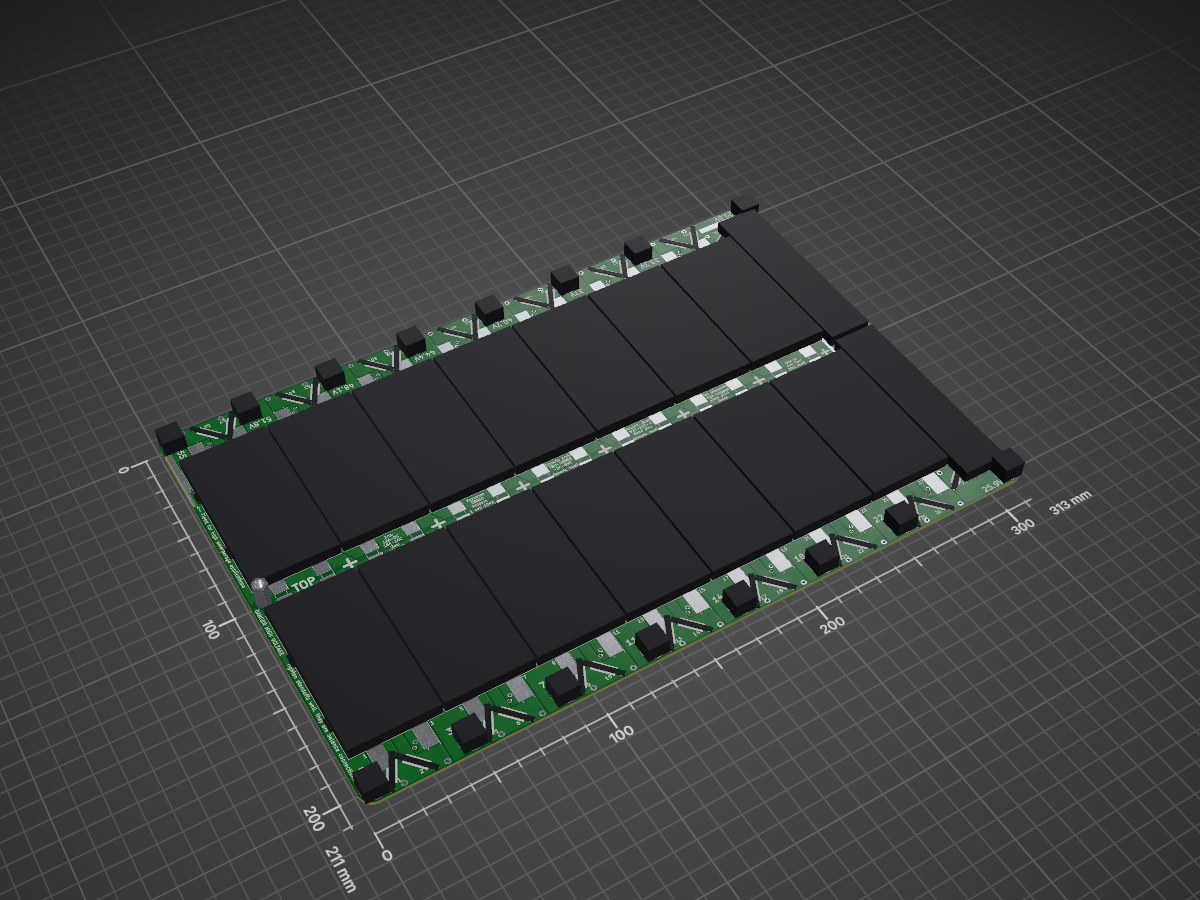
2 layers313 × 211 mm
 WannaBAcoder/PCB-Powerwalls21
File Repository for the DIY PCB Powerwall Community
15s4p board is an open-source printed circuit board by WannaBAcoder, from the WannaBAcoder/PCB-Powerwalls repository on GitHub. It is a 2-layer board of 313 × 211 mm with 174 parts on 76 nets, routed with 2 tracks and 0 vias.
Its parts include 60 fuses and 16 connectors.
This is the public file Repository for the DIY PCB Powerwalls Community. The projects are developed and maintained by Vinnie Maro and Shaun Bond.
We are developing a PCB alternative to common powerwall building techniques for 18650(and similar) batteries. This system has been developed with maintainability, expandability, and practicality in mind.
For additional DIY Powerwall building resources, please check out some of the many other active facebook groups and forums:
To see features currently in development or exploration, check out our issues page.
The 15s4p battery board is a stackable solution that reduces the amount of wiring required by placing all series and balance connections through standoffs that structurally connect the boards. Batteries mount to both sides of the PCB, in a variety of ways. Each cell is individually fused for added safety.
You can choose to use plastic cell holders that are available in many through-hole and surface mount packages. For the through-hole packages, you must bend the pins at a 90 degree angle so that the holders sit as flat as possible.


A cheaper alternative to plastic holders is spring clips. The clips work like traditional battery holders with springs, but these require the use of zip ties to hold the cells in place.


The last option is to use fuse wire. You will still need to use zip ties to hold the cells in place, but you can solder the fuse wire directly to the PCB pads, and remove the need for populating fuses(you will need to short the fuse pads to do this). You can also use large fuse wire and still use fuses, if desired. Spotwelding fuse wire to the batteries and soldering the other end to the PCB pads is recommended.


The 7s Adapter PCB was created to take our popular 15s4p design and convert it into a 7s8p PCB. We do this by leaving the out the 8s cells, which creates two 7s groups that get connected in parallel. It is recommended to use at least one of these adapter PCBs for every 5 boards, or 20A of main fuse(which is 10A load on each of these boards). This board also joins the battery stacks with standoffs. It's important to equally space these boards within a pack for best current distribution. For example, a 12 battery board stack could use 3 adapter boards, spaced every 4 boards.


The BMS/display adapter board helps the user connect a Moonitor, or a variety of BMS systems to the battery PCB stacks, and is capable of supporting ~5A balance current. This board also includes spaces to add series-level voltage displays, but they can be disabled if not desired. You can also use this board with the 7s adapter board configurations.


You can order your own boards from any number of PCB manufacturers. Many of our supporters use JLCPCB.com.
Recommended manufacturing options:
M4 Standoffs(40mm for SMD plastic holders, 45mm for through-hole plastic holders, may be able to make 40mm work with zip tie methods if zipties are alternated. Not confirmed at this time)
60x Glass Axial Fuses Choosing the right fuse is based on tradeoff between usebility and saftey. Even a 0.5A fuse can't protect against all 18650(and similar) failure modes. Shaun Bond's testing suggests 0.5A fuses are the ideal size for safety, but impractical for all massive builds with low load. You should still consider your pack-loading characteristics when choosing them.
**Be sure to choose the right holders for your desired build. For plastic holder builds, the quantities assume using only 1-cell and 2cell, or 3-cell and 4-cell holders per board.
Plastic Holders
4x 1-cell holder(Keystone 1042)
28x 2-cell holder(Keystone 1048)
4x 3-cell holder(BK-18650-PC6)(through-hole)
24x 4-cell holder(BK-18650-PC8)(through-hole)
120x Spring clips(Keystone 5331)
1x Total voltage pack voltage display(Adafruit 705)
15x Series-group voltage display(Seeed 114990163)
1x 12VDC 40x40mm PC Fan(2-wire)
1x 75VDC to 12V buck converter module.
1x 0.25A glass fuse
16x B4A Lugs
0.1" male pin headers
0.1" jumper blocks
Moonitor BMS
You can purchase this BMS from the Moonitor team on their website. You can also contact them directly for more information.
Check out the wiki for assembly instructions, and additional information.
Each powerwall PCB has its own revision in the form of VX.X. In addition to this, we version the entire system package in a release in the form of RX.0. See the latest release for the most recent hardware package. Whenever any of the hardware in a package changes, the PCB version and package release will be updated. PCB versions are printed on all PCBs for easy identification.
Although the kicad source files are available, the safety considerations that go into this project make it potentially unsafe to modify; do so at your own risk! You can always contribute to the development of this project by suggesting improvements or new features desired by reporting them as issues.
This project is licensed under the CERN Open Hardware License - see the LICENSE.txt file for details.
A special thank you to the people and communities that inspired or helped develop the early versions of this hardware and helped others realize the growing potential for these designs:
| Qty | Value | Footprint | References |
|---|---|---|---|
| 60 | Fuse_Small | 1048:fuse | F1, F2, F10, F11, F12, F13, F14, F15, F16, F17, F18, F19, F20, F21, F22, F23 +44 |
| 28 | Battery_Cell | 1048:2cell_dual_holder_longer | BT1, BT2, BT10, BT11, BT12, BT13, BT14, BT15, BT16, BT17, BT18, BT19, BT20, BT22, BT23, BT24 +12 |
| 4 | Battery_Cell | 1048:single_cell_dual_holder | BT21, BT26, BT27, BT32 |
| 1 | 0V | 1048:hole | J6 |
| 1 | 11.1V | 1048:hole | J3 |
| 1 | 14.8V | 1048:hole | J2 |
| 1 | 18.5V | 1048:hole | J1 |
| 1 | 22.2V | 1048:hole | J11 |
| 1 | 25.9V | 1048:hole | J10 |
| 1 | 29.6V | 1048:hole | J9 |
| 1 | 3.7V | 1048:hole | J5 |
| 1 | 33.3V | 1048:hole | J8 |
| 1 | 37V | 1048:hole | J7 |
| 1 | 40.7V | 1048:hole | J16 |
| 1 | 44.4V | 1048:hole | J15 |
| 1 | 48.1V | 1048:hole | J14 |
| 1 | 51.8V | 1048:hole | J13 |
| 1 | 55.5V | 1048:hole | J12 |
| 1 | 7.4V | 1048:hole | J4 |
The 108 most common of 174 parts.


nkrackow/SingularitySurfer-FPGA-Lock-In-Amplifier
Repository for the development of an FPGA based DSP Lock-In Amplifier


doppelhub/Honda_Insight_LiBCM
Replacement BCM for G1 Honda Insight Lithium Conversion


alexcamlo/winsplit
Inspired by the Boardrun Bizarre and Red herring. I wanted to be able to use a normal keyset, so no full ortho, but split.

It measures 313 × 211 mm and has 2 copper layers, 1.6 mm thick.
174 parts. The full list of its parts is on this page, with links to each part's symbol and footprint where PCBKit's library has them.
From the WannaBAcoder/PCB-Powerwalls repository on GitHub, at the commit this page was made from: the board is 15s4p_PCB/15s4p_board.kicad_pcb. PCBKit opens the board in the browser, with nothing to install.
Its repository states no licence, so its author keeps all rights: ask WannaBAcoder before reusing the design.
