

2 layers35 × 38.4 mm
Handgelenk
Jeija/esp8266-smartwatch
ESP8266 DIY WiFi Smartwatch with MPU-9250, RTC, OLED, FT232, ...
61 parts233
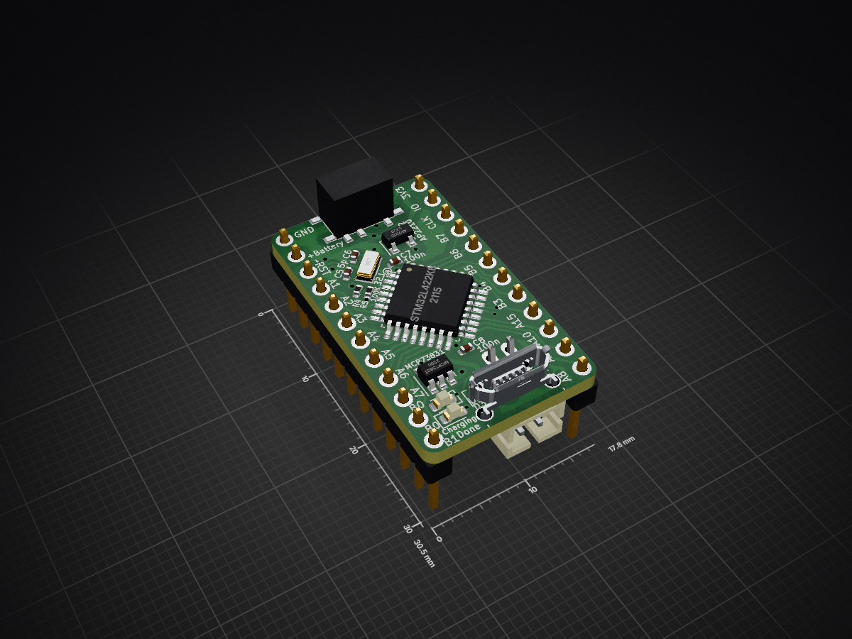
 WRansohoff/STM32_LiPo_Example17
Simple lithium battery-powered STM32 board using an MCP73831 for charging.
STM32L422KB LiPo is an open-source printed circuit board by WRansohoff, from the WRansohoff/STM32_LiPo_Example repository on GitHub, published under the MIT licence. It is a 2-layer board of 17.8 × 30.5 mm with 29 parts on 37 nets, routed with 319 tracks and 28 vias.
It is built around the STM32L422KBT6 and MCP73831. Its parts include 11 capacitors, 5 resistors, 4 connectors, 3 ICs and 2 diodes. It belongs with the power boards and the STM32 boards of this library.
This is a small board which incorporates an MCP73831 Lithium battery charger. It has a maximum charge rate of 500mA, but it is simple and easy to use. A JST PH-2 connector is used for the battery; it seems like small lithium batteries have more or less standardized on this type of connector, but double-check the polarity before you plug anything in.
A micro-USB plug is used as a 5V supply to charge the battery, and a small slide switch is used to turn the board's power on or off. Two 100KΩ resistors also form a voltage divider for the microcontroller to read the battery voltage through pin A0's ADC channel, and I'm planning to add an example firmware which reads and prints the battery voltage over UART in the near future.
This board will not work with the almost-identical MCP73832 chip - the difference is that the 'status' pin has a tri-state output on the MCP73831 and an open-drain output on the MCP73832. So with the former, you can have separate 'charging in progress' and 'done charging' LEDS. But with the latter, you can only have one 'done charging' LED directly connected to the pin. I dunno, maybe that saves you $.005 per unit when you order 10 million at a time or something.
As seen through OSHPark's purple-colored glasses:
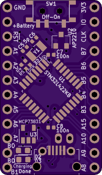
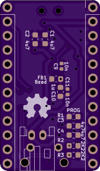
Before assembling this board or trying to incorporate elements into your design, spend some time ressearching lithium battery safety precautions. Always independently verify lithium battery circuits before assembling them. Never leave lithium batteries unattended when they are charging or in use.
Here's a link to the datasheet for the battery-charging chip. Double-check your designs against its recommendations:
http://ww1.microchip.com/downloads/en/DeviceDoc/20001984g.pdf
I'm not even going to try to make a comprehensive list of safety precautions to take when handling lithium batteries, and working with circuitry that interacts with them is even more dangerous. Do your own research on how to work with them safely, start out with small batteries in the 100s of milliAmp-hours, and most importantly, don't blame me if anything goes wrong. The MIT license is very permissive, but it also says there's no warranty :)
I should use a voltage regulator with a 'power good' pin and connect it to the reset line, to reduce problems with power supply glitches when the battery gets low.
I haven't tested the USB data lines, and if they do work, there isn't much space to add the optional-but-recommended TVS diodes such as an SP0503BAHT. It might be better to use a cheaper microcontroller and only use the USB port for power.
There's no "heartbeat" LED, and it's nice to have at least one user-controlled LED on a board for all kinds of reasons. For one thing, there's no way for the board to indicate that it has a low battery.
I need to polish a simple test firmware which reads the battery voltage and prints it out over UART every few seconds.
It's usually silly to use a linear voltage regulator in a simple battery-powered application, because you waste a bunch of power. Using a buck converter would be a better choice here.
Per #1, I should connect the MCP73831 ground pin to a larger ground plane to help it dissipate heat and maybe reach its maximum charge current of 500mA.
It might be a good idea to move the 'Ground' and '+Battery' breadboard pins farther apart, to make accidental shorts less likely.
| Qty | Value | Footprint | References |
|---|---|---|---|
| 4 | 4u7 | Capacitor_SMD:C_0603_1608Metric | C1, C2, C3, C4 |
| 2 | 100K | Resistor_SMD:R_0402_1005Metric | R4, R5 |
| 2 | 100n | Capacitor_SMD:C_0402_1005Metric | C7, C8 |
| 2 | 10n | Capacitor_SMD:C_0402_1005Metric | C9, C11 |
| 2 | 2K2 | Resistor_SMD:R_0603_1608Metric | R2, R3 |
| 2 | 5p | Capacitor_SMD:C_0402_1005Metric | C5, C6 |
| 1 | 1u | Capacitor_SMD:C_0603_1608Metric | C10 |
| 1 | AP2210 | Package_TO_SOT_SMD:SOT-23 | U2 |
| 1 | Battery | Connector_JST:JST_PH_S2B-PH-K_1x02_P2.00mm_Horizontal | J5 |
| 1 | Bead | Resistor_SMD:R_0603_1608Metric | FB1 |
| 1 | Charging | LED_SMD:LED_0603_1608Metric | D2 |
| 1 | Done | LED_SMD:LED_0603_1608Metric | D3 |
| 1 | GPIO1 | Connector_PinHeader_2.54mm:PinHeader_1x12_P2.54mm_Vertical | J2 |
| 1 | GPIO2 | Connector_PinHeader_2.54mm:PinHeader_1x12_P2.54mm_Vertical | J3 |
| 1 | LOGO | STM32L422KB_LiPo:oshw_logo | G*** |
| 1 | LSE | Crystal:Crystal_SMD_3215-2Pin_3.2x1.5mm | Y1 |
| 1 | MCP73831 | Package_TO_SOT_SMD:SOT-23-5 | U3 |
| 1 | Off-On | STM32L422KB_LiPo:mini_slide_switch | SW1 |
| 1 | PROG | Resistor_SMD:R_0603_1608Metric | R1 |
| 1 | STM32L422KB | Package_QFP:LQFP-32_7x7mm_P0.8mm | U1 |
| 1 | uUSB | STM32L422KB_LiPo:MyMicroUSB | J1 |
Jeija/esp8266-smartwatch
ESP8266 DIY WiFi Smartwatch with MPU-9250, RTC, OLED, FT232, ...


azerimaker/Penguino-STM32WL-LoRa-E5
This repo contains all the necessary design and fabrication files for the Seeed Studio LoRa-E5 based Penguino Feather breakout board.

Mposiblee/Zireael
The keyboard is based on Dao Chok BLE. The locations of components on the board have been changed, space for the battery has been added, and the thumb cluster has also been changed.


xavierbasc/dm50
DM50 is a cheap, powerful, easy to build, open source hardware, and high precision calculator.

It measures 17.8 × 30.5 mm and has 2 copper layers, 1.6 mm thick.
29 parts, built around the STM32L422KBT6 and MCP73831. The full list of its parts is on this page, with links to each part's symbol and footprint where PCBKit's library has them.
From the WRansohoff/STM32_LiPo_Example repository on GitHub, at the commit this page was made from: the board is STM32L422KB_LiPo.kicad_pcb. PCBKit opens the board in the browser, with nothing to install.
Its repository publishes it under the MIT licence: you may reuse it on that licence's terms (keep the author's notice, and for a copyleft licence share your changes alike).