4 layers49.5 × 35.2 mm

 WRansohoff/MotoMate1
An STM32-based GPS receiver handheld board with a small display and microSD card slot: eventually, I'd like to make some simple mapping / logging firmware and a case for mounting it to motorcycle handlebars.
MotoMate is an open-source printed circuit board by WRansohoff, from the WRansohoff/MotoMate repository on GitHub, published under the MIT licence. It is a 2-layer board of 92.3 × 50.2 mm with 63 parts on 82 nets, routed with 799 tracks and 118 vias.
It is built around the LDFM33PVR and MCP73831. Its parts include 18 capacitors, 11 connectors, 8 resistors, 6 diodes and 6 switches. It belongs with the radio and wireless boards and the STM32 boards of this library.


This is a small board designed to act as a handheld GPS receiver, and eventually (I hope) a handlebar-mounted GPS mapper / tracker for offroad motorcycling.
The microcontroller core is an STM32L496Rx chip - I recommend the STM32L496RGT3, because it costs less than $1 to get an extra 512KB of Flash (although the chip itself is more like $10). The 320KB of built-in RAM is enough to store a 150KB framebuffer for the 320x240 16bpp ILI9341 display, but it doesn't leave much room for storage-intensive algorithms such as image processing. Still, there's no external storage to worry about besides the microSD card.
The board is wired to use hardware periphererals for driving the SD/MMC interface, USB OTG, SPI for the display, and UART for talking to a "GY-NEO6MV2" GPS module. I've noticed that some listings for these u-blox Neo-6M-based GPS modules have red-colored boards with pinouts that won't work with this design; look for blue-colored ones and double-check the pinouts against the schematic. I might update the design to use the module itself instead of a cheap breakout board in the future, but for now, sorry for the inconvenience.
There's also a single-channel audio amplifier connected to one of the chip's DACs with a mute switch, and some ADCs are used to monitor a photodiode and the board's battery voltage. And there are pads exposed for an extra UART and I2C connection, and seven button inputs split across two tactile buttons and a 'navigation switch'. The buttons are assigned to pins so that there shouldn't be any conflicts with EXTI lines when setting up interrupts to listen for presses.
I'll write up more comprehensive information (and upload some proper gerber files) once I've had a chance to test this revision and upload some basic test firmwares to confirm the board's various functions.
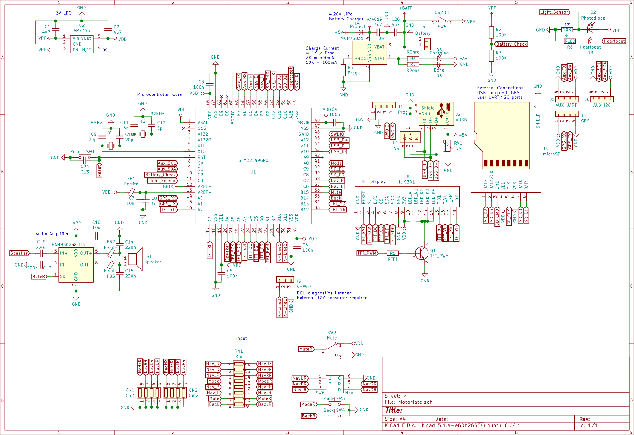
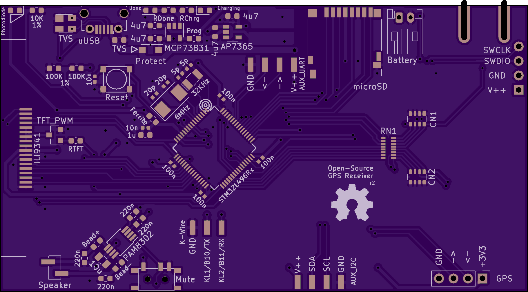
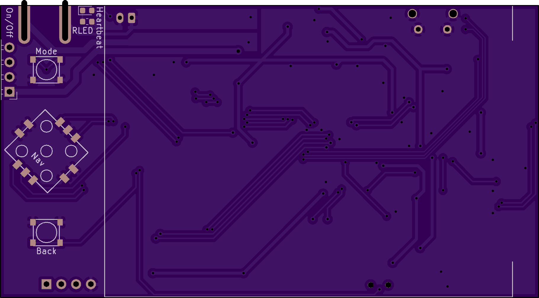
I've assembled an earlier version of this design and confirmed that most parts of the design work, but I haven't written a comprehensive "GPS mapper" firmware yet. The first version has too much space between the TFT ribbon connector and the edge of the board to fold the display over the USB connector and mute switch, so it was awkward to handle. I hope that this version will fit together better, but I haven't received it yet for testing.
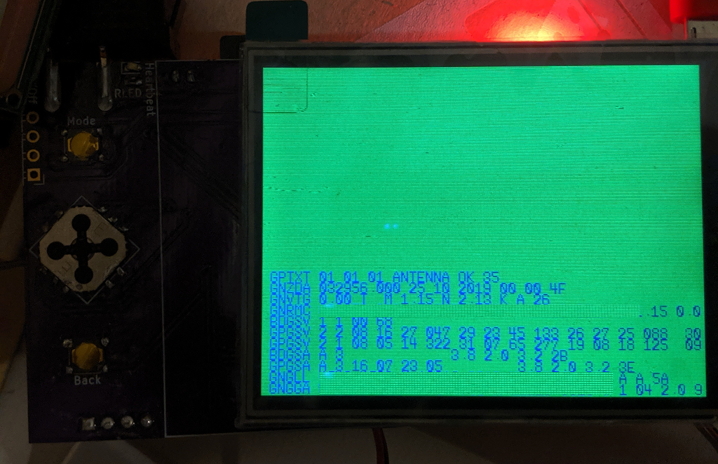
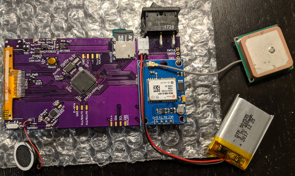
Sorry that I didn't get a better picture of the lit-up TFT; it's hard to take pictures of backlit displays, and it's not that important anyways. I also edited one of the images to remove the actual GPS coordinates, because I didn't feel like driving out to the middle of the woods to take a picture.
Anyways, so far I've tested (or not) the following parts:
Battery monitoring: the 'charging' and 'done' LEDs seem to reflect the charge status, and the 12-bit ADC reads close to 4.2V on a full charge using the formula: VBatt = ( ADC * 2 / 4095 ) * 3.3. Note that for an accurate reading, you need to set one of the highest sampling times (250-650 cycles) due to the low amount of current flowing through the voltage divider.
TFT display: The backlight can be adjusted with a PWM signal, and the SPI peripheral can be used with DMA to draw a framebuffer to the display. This makes it much easier to test other parts of the board :)
GPS module: Appears to work, although I haven't tried configuring it with anything other than the default settings. After placing the antenna with a clear view of the sky and letting it acquire a few satellites, it reports latitude and longitude readings that appear to be accurate to within maybe 5 meters or so.
microSD card: Not tested.
Buttons: Tested using falling-edge interrupts with the pins configured as inputs with pull-up resistors enabled. These low-profile buttons are really designed to be used with a case that has plastic or rubber 'pegs' connected to larger buttons, though.
Auxiliary UARTs and I2C: Not tested.
'Heartbeat' LED: Works.
Photodiode: Not tested; in the first revision of the board, I put the photodiode underneath where the display's ribbon connector folded over, so it was always in darkness. D'oh!
Speaker: Works well enough to play a sine wave accurately enough for a tuner to read the desired note. I haven't tried playing music or speech though, and it probably wouldn't do that very well. This is only a 12-bit DAC with poor filtering, after all. The speaker is mostly intended for beeps, buzzes, and chirps.
See firmware/ for the source code used to run those tests, and fw_lib/ for some shared helper functions.
| Qty | Value | Footprint | References |
|---|---|---|---|
| 4 | 100n | Capacitor_SMD:C_0402_1005Metric | C3, C4, C5, C6 |
| 4 | 4u7 | Capacitor_SMD:C_0603_1608Metric | C1, C2, C19, C20 |
| 2 | 100K | Resistor_SMD:R_0603_1608Metric | R2, R3 |
| 2 | 10n | Capacitor_SMD:C_0402_1005Metric | C7, C13 |
| 2 | 20p | Capacitor_SMD:C_0402_1005Metric | C9, C10 |
| 2 | 220n | Capacitor_SMD:C_0603_1608Metric | C16, C17 |
| 2 | 5p | Capacitor_SMD:C_0402_1005Metric | C11, C12 |
| 1 | 10K | Resistor_SMD:R_0603_1608Metric | R4 |
| 1 | 10u | Capacitor_SMD:C_0805_2012Metric | C18 |
| 1 | 1u | Capacitor_SMD:C_0603_1608Metric | C8 |
| 1 | 32KHz | Crystal:Crystal_SMD_EuroQuartz_EQ161-2Pin_3.2x1.5mm | Y2 |
| 1 | 8MHz | Crystal:Crystal_SMD_Abracon_ABM3-2Pin_5.0x3.2mm | Y1 |
| 1 | AUX_I2C | MotoMate:Conn_01x04_H_SMD | J6 |
| 1 | AUX_UART | MotoMate:Conn_01x04_H_SMD | J5 |
| 1 | Back | MotoMate:Snap_Tac_Switch_SMT | SW4 |
| 1 | Battery | Connector_JST:JST_PH_S2B-PH-K_1x02_P2.00mm_Horizontal | J7 |
| 1 | Bead+ | Resistor_SMD:R_0603_1608Metric | FB2 |
| 1 | Bead- | Resistor_SMD:R_0603_1608Metric | FB3 |
| 1 | Charging | LED_SMD:LED_0603_1608Metric | D5 |
| 1 | Cin1 | Resistor_SMD:R_Array_Convex_4x0603 | CN1 |
| 1 | Cin2 | Resistor_SMD:R_Array_Convex_4x0603 | CN2 |
| 1 | Done | LED_SMD:LED_0603_1608Metric | D6 |
| 1 | Ferrite | Resistor_SMD:R_0603_1608Metric | FB1 |
| 1 | GPS | Connector_PinHeader_2.54mm:PinHeader_1x04_P2.54mm_Vertical | J4 |
| 1 | Heartbeat | LED_SMD:LED_0603_1608Metric | D3 |
| 1 | ILI9341 | MotoMate:ILI9341_18P_0.8mm | J8 |
| 1 | K-Wire | MotoMate:Conn_01x03_H_SMD | J9 |
| 1 | LDFM33 | MotoMate:ST_LDFM_2x2DFN | U2 |
| 1 | LOGO | MotoMate:oshw_logo | G*** |
| 1 | MCP73831 | Package_TO_SOT_SMD:SOT-23-5 | U4 |
| 1 | Mode | MotoMate:Snap_Tac_Switch_SMT | SW3 |
| 1 | Mute | MotoMate:mini_slide_switch | SW2 |
| 1 | Nav | MotoMate:NavSwitch_SMT | SW6 |
| 1 | On/Off | MotoMate:mini_slide_switch | SW5 |
| 1 | PAM8302 | Package_SO:MSOP-8_3x3mm_P0.65mm | U3 |
| 1 | Photodiode | LED_SMD:LED_0603_1608Metric | D2 |
| 1 | Prog | Connector_PinHeader_2.54mm:PinHeader_1x04_P2.54mm_Horizontal | J1 |
| 1 | Prog | Resistor_SMD:R_0603_1608Metric | R5 |
| 1 | Protect | Diode_SMD:D_SOD-123F | D4 |
| 1 | RChrg | Resistor_SMD:R_0603_1608Metric | R6 |
| 1 | RDone | Resistor_SMD:R_0603_1608Metric | R7 |
| 1 | RLED | Resistor_SMD:R_0603_1608Metric | R8 |
| 1 | RTFT | Resistor_SMD:R_0603_1608Metric | R1 |
| 1 | Reset | MotoMate:Snap_Tac_Switch_SMT | SW1 |
| 1 | Rin | Resistor_SMD:R_Array_Convex_8x0602 | RN1 |
| 1 | STM32L496Rx | MotoMate:LQFP-64_10x10mm_P0.5mm | U1 |
| 1 | Speaker | Connector_PinHeader_2.00mm:PinHeader_1x02_P2.00mm_Vertical_SMD_Pin1Left | LS1 |
| 1 | TFT_PWM | Package_TO_SOT_SMD:SOT-23 | Q1 |
| 1 | TVS | Resistor_SMD:R_0603_1608Metric | RV1 |
| 1 | TVS | Package_TO_SOT_SMD:SOT-143 | D1 |
| 1 | microSD | Connector_Card:microSD_HC_Hirose_DM3D-SF | J3 |
| 1 | uUSB | MotoMate:MyMicroUSB | J2 |

Jeija/esp8266-smartwatch
ESP8266 DIY WiFi Smartwatch with MPU-9250, RTC, OLED, FT232, ...


azerimaker/Penguino-STM32WL-LoRa-E5
This repo contains all the necessary design and fabrication files for the Seeed Studio LoRa-E5 based Penguino Feather breakout board.

Mposiblee/Zireael
The keyboard is based on Dao Chok BLE. The locations of components on the board have been changed, space for the battery has been added, and the thumb cluster has also been changed.


xavierbasc/dm50
DM50 is a cheap, powerful, easy to build, open source hardware, and high precision calculator.
It measures 92.3 × 50.2 mm and has 2 copper layers, 1.6 mm thick.
63 parts, built around the LDFM33PVR and MCP73831. The full list of its parts is on this page, with links to each part's symbol and footprint where PCBKit's library has them.
From the WRansohoff/MotoMate repository on GitHub, at the commit this page was made from: the board is MotoMate.kicad_pcb. PCBKit opens the board in the browser, with nothing to install.
Its repository publishes it under the MIT licence: you may reuse it on that licence's terms (keep the author's notice, and for a copyleft licence share your changes alike).