
4 layers31.6 × 84.1 mm
MCL68
MicroCoreLabs/Projects
Ted Fried's MicroCore Labs Projects - FPGA CPU cores and emulators for the 8088, 8086, 8051, 6502, 68000, Z80, Risc-V, and also Typewriter and EPROM Emulator projects.
13 parts534
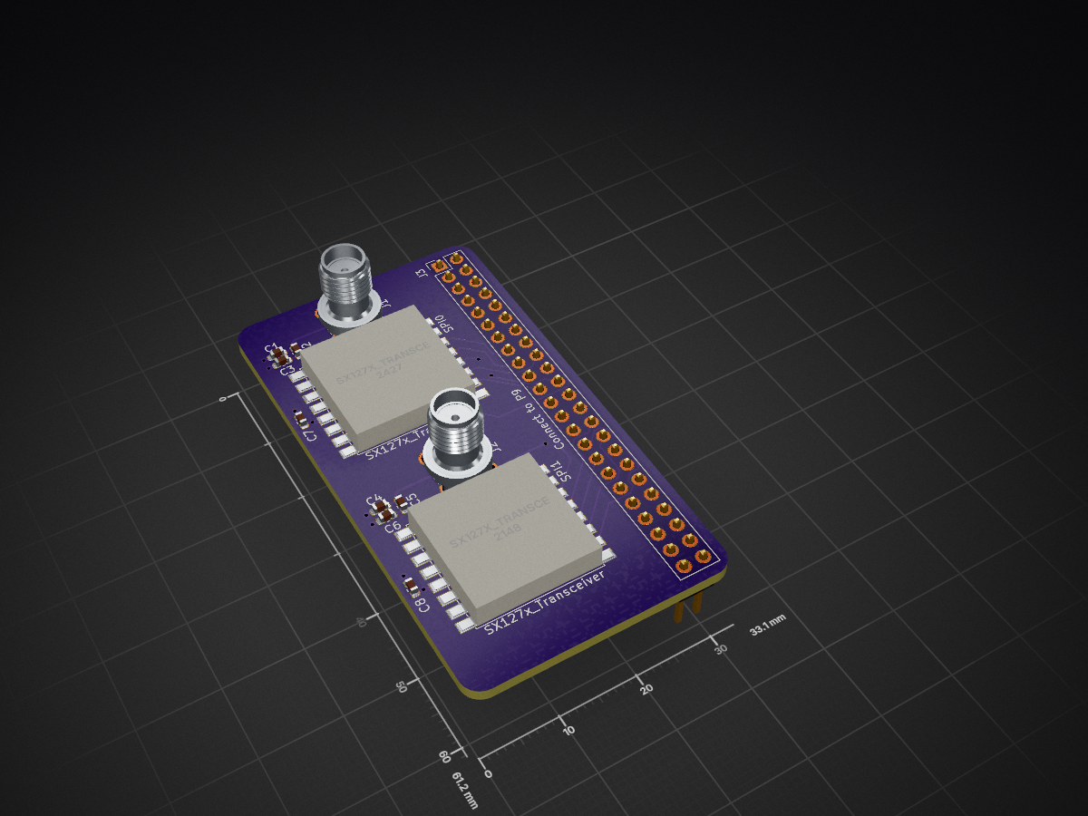
 VioletEternity/BeagleBoneLoRaAdapter1
Dual LoRa module adapter for BeagleBone
BeagleBoneLoRaAdapter is an open-source printed circuit board by VioletEternity, from the VioletEternity/BeagleBoneLoRaAdapter repository on GitHub, published under the CERN-OHL-P-2.0 licence. It is a 4-layer board of 33.1 × 61.2 mm with 13 parts on 54 nets, routed with 102 tracks and 11 vias.
It is built around the TSW-125-07-G-D. Its parts include 8 capacitors, 3 connectors and 2 ICs. It belongs with the radio and wireless boards of this library.
This PCBA connects widely available LoRa modules based on Semtech SX127x RFIC, such as this module (archive) sold on Aliexpress for less than $3, to the Texas Instruments BeagleBone family of single board computers.
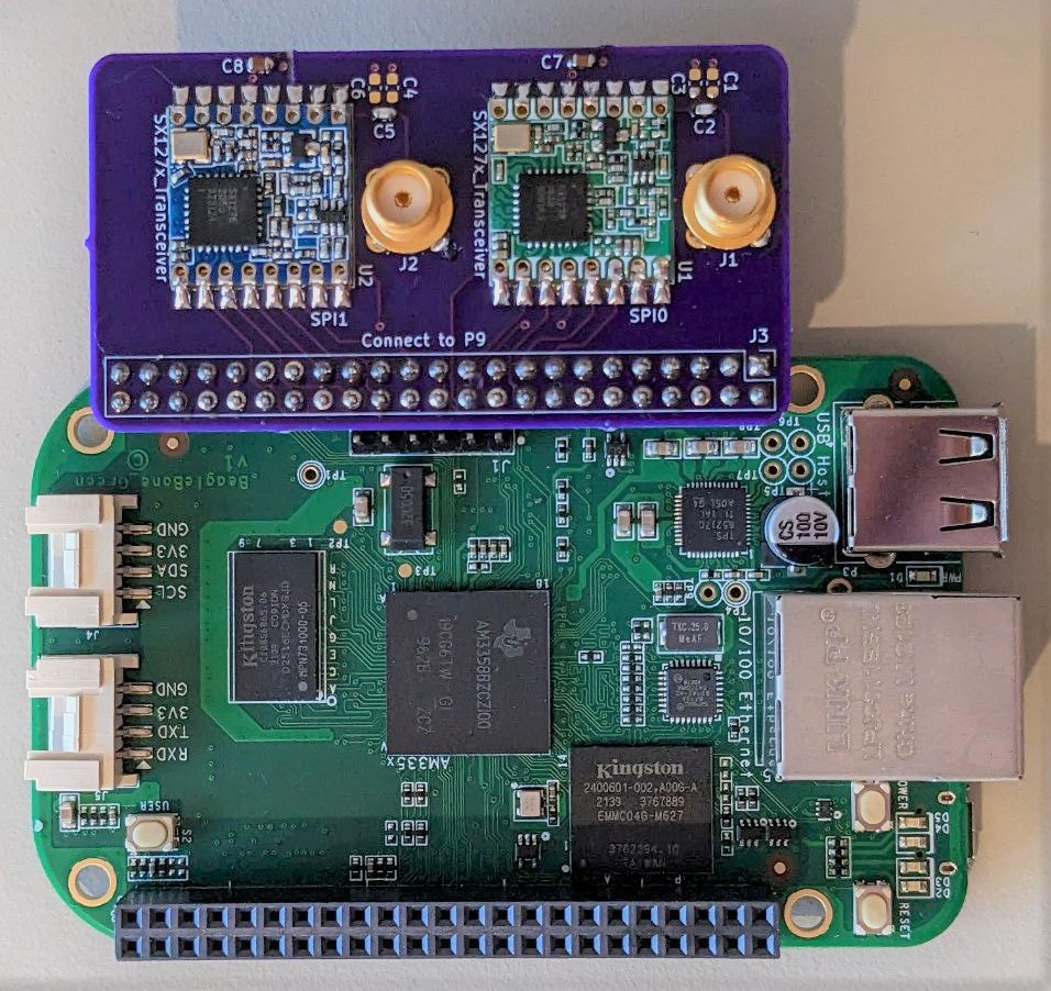
The module must have a size of 16 by 16 mm, and have 16 castellated pads with 2 mm spacing; for details, see the Kicad footprint. The module pinout must match the following, viewed from the top:
| Pin 1? | ||
|---|---|---|
| ANT | GND | |
| GND | DIO5 | |
| DIO3 | nRESET | |
| DIO4 | nCS | |
| 3V3 | SCK | |
| DIO0 | MOSI | |
| DIO1 | MISO | |
| DIO2 | GND |
These modules do not have a clearly marked pin 1, so the actual pinout may be rotated 180° compared to the above.
See also the bill of materials.
The following table lists the BeagleBone pins and their connections:
| Radio# | Function | BB pin | CPU pin |
|---|---|---|---|
| radio0 | nRESET | P9_15 | gpio1[16] |
| radio0 | IRQ | P9_16 | gpio1[19] |
| radio0 | nCS | P9_17 | gpio0[5] |
| radio0 | SCK | P9_22 | gpio0[2] |
| radio0 | MOSI | P9_18 | gpio0[4] |
| radio0 | MISO | P9_21 | gpio0[3] |
| radio1 | nRESET | P9_25 | gpio3[21] |
| radio1 | IRQ | P9_27 | gpio3[19] |
| radio1 | nCS | P9_28 | gpio3[17] |
| radio1 | SCK | P9_31 | gpio3[14] |
| radio1 | MOSI | P9_30 | gpio3[16] |
| radio1 | MISO | P9_29 | gpio3[15] |
Radio 0 is connected to CS0 of SPI0, radio 1 is connected to CS0 of SPI1.
To configure BeagleBone pins, run the following commands:
sudo modprobe spidev
sudo chown $USER /dev/spidev*

config-pin P9_15 gpio_pu
config-pin P9_16 gpio_pu
config-pin P9_17 spi_cs
config-pin P9_22 spi_sclk
config-pin P9_18 spi
config-pin P9_21 spi

config-pin P9_25 gpio_pu
config-pin P9_27 gpio_pu
config-pin P9_28 spi_cs
config-pin P9_31 spi_sclk
config-pin P9_30 spi
config-pin P9_29 spi
These commands were tested on Debian 12 (bookworm).
To perform a basic test of module functionality, install spi-tools and run the following commands:
echo '0: 4200' | xxd -r | spi-pipe -b 2 -d /dev/spidev0.0 | xxd
echo '0: 4200' | xxd -r | spi-pipe -b 2 -d /dev/spidev1.0 | xxd
Both commands should return the following output:
00000000: 0012 ..The number 12 is the module ASIC revision.
Steps for performing a full test of module functionality, including radio transmission and reception, will be provided later.
A1 : Initial revision
The adapter is covered by the CERN-OHL-P (permissive) license. See LICENSE.txt for details.
| Qty | Value | Footprint | References |
|---|---|---|---|
| 4 | DNP | Capacitor_SMD:C_0603_1608Metric | C1, C3, C4, C6 |
| 2 | 10u | Capacitor_SMD:C_0603_1608Metric | C7, C8 |
| 2 | 220p | Capacitor_SMD:C_0603_1608Metric | C2, C5 |
| 2 | Conn_Coaxial | Library:SMA_Cinch_142-0701_Vertical | J1, J2 |
| 2 | SX127x_Transceiver | Library:LoRaModule-16_16.0x16.0mm_Layout2x8_P2.0mm | U1, U2 |
| 1 | Conn_02x23_Odd_Even | Connector_PinHeader_2.54mm:PinHeader_2x23_P2.54mm_Vertical | J3 |
MicroCoreLabs/Projects
Ted Fried's MicroCore Labs Projects - FPGA CPU cores and emulators for the 8088, 8086, 8051, 6502, 68000, Z80, Risc-V, and also Typewriter and EPROM Emulator projects.

AzonInc/Doorman
ESP32-S3 based Intercom Gateway (TCS / Koch / Niko / Scantron / Analogue Systems)

loxodes/vna
Under development open hardware microwave vector network analyzer


Protocentral/healthypi-move-hw
Hardware files for the HealthyPi Move


felixheld/qspimux
QSPI flash multiplexer - connect a SPI NOR flash to either an embedded system or a programmer for remote firmware tests

Unified-Daughterboard/UDB-C-EZM
For more details on the Unified Daughterboard project, see the main website.
It measures 33.1 × 61.2 mm and has 4 copper layers, 1.57 mm thick.
13 parts, built around the TSW-125-07-G-D. The full list of its parts is on this page, with links to each part's symbol and footprint where PCBKit's library has them.
From the VioletEternity/BeagleBoneLoRaAdapter repository on GitHub, at the commit this page was made from: the board is BeagleBoneLoRaAdapter.kicad_pcb and its schematic BeagleBoneLoRaAdapter.kicad_sch. PCBKit opens the board in the browser, with nothing to install.
Its repository publishes it under the CERN-OHL-P-2.0 licence: you may reuse it on that licence's terms (keep the author's notice, and for a copyleft licence share your changes alike).