
2 layers61 × 177.8 mm
Motor control + ESP
Scramtv/ESD_P5
Github repo for our group through fifth semester of Electronics and Systems design on AAU.
16 parts

 Vinomakon/VEPR-Robotarm
A personal robotics project bringing together a 3D-printed six-axis arm, custom motor-driver electronics, ESP32 firmware, and a Python desktop control panel.
Driver Carrier v2 is an open-source printed circuit board by Vinomakon, from the Vinomakon/VEPR-Robotarm repository on GitHub. It is a 2-layer board of 95 × 100 mm with 33 parts on 74 nets, routed with 463 tracks and 175 vias.
It is built around the ESP32-S3-DEVKITM-1-N8. Its parts include 17 connectors, 7 ICs and 6 capacitors. It belongs with the robots and motor control boards and the ESP32 boards of this library.
A personal robotics project bringing together a 3D-printed six-axis arm, custom motor-driver electronics, ESP32 firmware, and a Python desktop control panel.
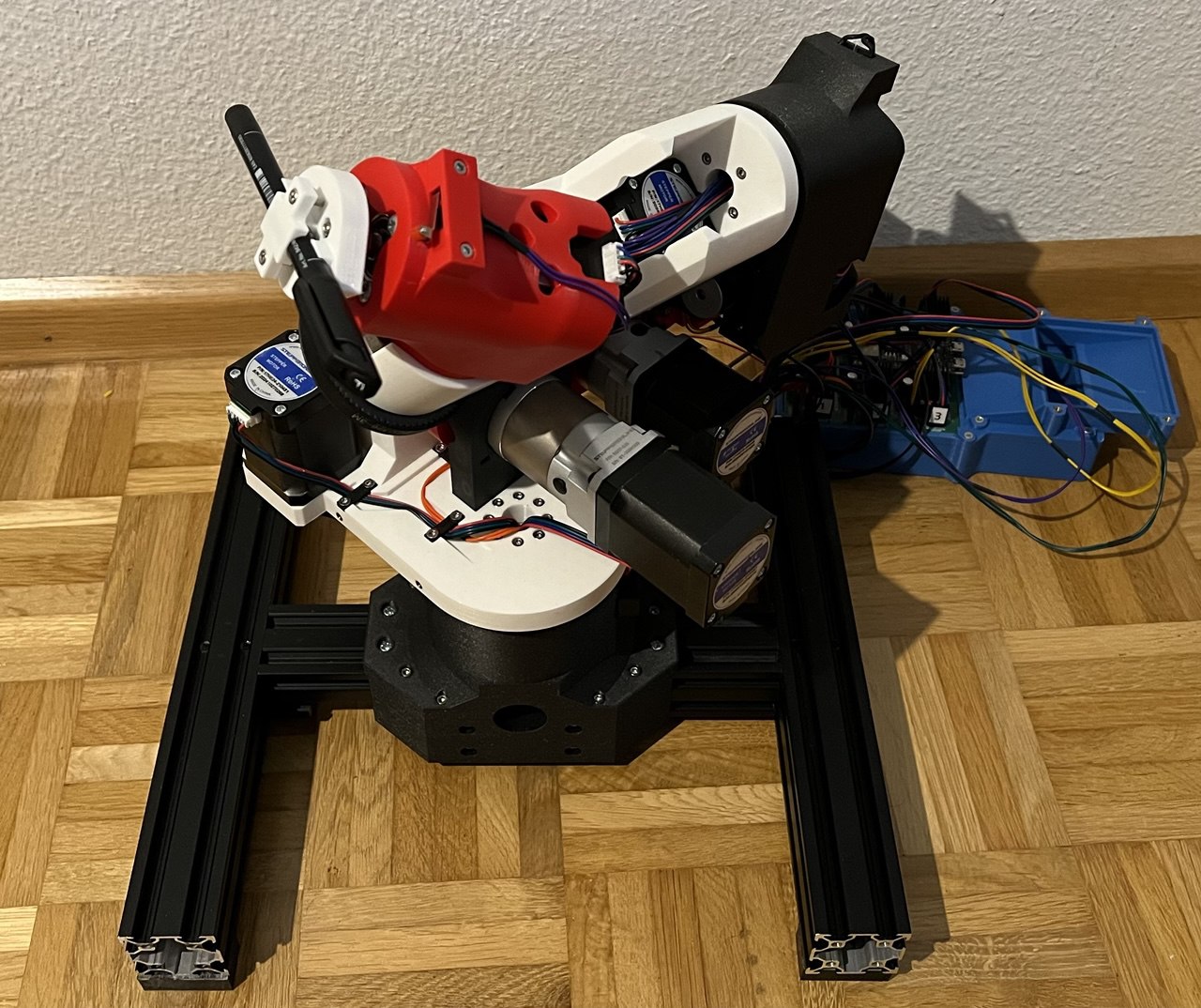
VEPR was built from the ground up to explore mechanical design, electronics, embedded programming, and robotics in one working system. Its six rotary joints control the position and orientation of an end effector, with a Python interface for joint-level control and forward/inverse kinematics.
The arm combines 3D-printed parts with belt drives, planetary gearboxes, and bearing supports. A custom carrier board connects an ESP32-S3 controller to the motor drivers and homing switches.
Originally developed as a Swiss Maturaarbeit, this repository collects the core engineering files in a layout intended for others to explore. The original German report explains the design decisions, mechanical iterations, electronics, and kinematics: read the project documentation.
| Part | Implementation described in the project documentation |
|---|---|
| Structure | Six rotary joints, with printed PLA parts and PC-CF at selected hot or highly loaded locations |
| Drive system | NEMA-17 stepper motors, belt reductions, and planetary gearboxes |
| Motor control | TMC5160 drivers, STEP/DIR motion control, and SPI configuration |
| Homing | Mechanical limit switches |
| Controller | ESP32-S3-DevKitM-1 running Arduino-framework firmware |
| Communication | Wi-Fi access point and WebSocket commands |
| Desktop software | Python, Tkinter, and NumPy, with local JSON configuration |
The report documents the earlier Gradio interface. This repository retains the newer Tkinter-based VEPR-Control v2 application; setup instructions follow that source code.
| Folder | Contents |
|---|---|
software/python/ | Desktop app, its data, dependency list, and setup notes |
firmware/controller/ | Fuller controller implementation from the original 6-Axis-Robotarm project |
firmware/experimental/ | Separate, incomplete modular firmware variant; see firmware notes |
hardware/cad/ | Main CAD folder; original subfolders and filenames preserved |
hardware/electronics/ | Carrier-board designs and custom KiCad libraries |
hardware/ | Bill of materials and motor wiring workbook |
docs/ | Original report and its sources, migration record, and supporting images |
See Python setup. The application starts with data transfer disabled, allowing the interface to be explored before connecting the arm. Physical operation has not been validated as part of this repository reorganization.
Open firmware/controller/ as a PlatformIO project. Its board setting is esp32-s3-devkitm-1; the environment is named esp32-s3-devkitc-1 in the original configuration. Both names have been preserved. Dependencies are declared in platformio.ini.
The controller creates a Wi-Fi access point and exposes a WebSocket at /ws. The Python client currently targets ws://192.168.4.1/ws. The controller source contains its existing access-point settings. Confirm your hardware, wiring, current settings, and calibration before enabling physical motion.
Read firmware notes, CAD notes, and electronics notes before selecting a design or firmware variant.
The repository preserves multiple mechanical revisions and two firmware implementations. The controller implementation is the starting point selected from source inspection; a confirmed hardware/software release is still to be identified. See remaining release details.
The tracked report has unfinished results sections, so this README does not assign numerical reach, payload, speed, accuracy, or repeatability ratings. The existing accuracy-test image is included as supporting material.
Created by Vinomakon. This curated snapshot comes from 6-Axis-Robotarm at commit 094f978.
The copied engineering files are unchanged. School administration, work journals, old software experiments, caches, automatic backups, and redundant outputs remain in the original repository. See the migration notes for the selection rationale.
A project license has not yet been selected. Public visibility alone does not grant permission to reuse the files. Any third-party assets retain their own terms; attribution and redistribution terms need review before publication.
| Qty | Value | Footprint | References |
|---|---|---|---|
| 6 | 100uF/50V 20% | Capacitor_THT:CP_Radial_D8.0mm_P3.50mm | C1, C2, C3, C4, C5, C6 |
| 6 | Conn_01x04_Pin | Connector_PinHeader_2.54mm:PinHeader_1x04_P2.54mm_Vertical | J1, J2, J3, J4, J5, J6 |
| 6 | SILENTSTEPSTICK TMC2130 | Custom_Footprints:SILENTSTEPSTICK TMC2130 | U1, U2, U3, U4, U5, U6 |
| 2 | Screw_Terminal_01x02 | Custom_Footprints:Phoenix_TerminalBlock_1x02_3.5mm_1984617 | J14, J15 |
| 1 | CAN Connector | Connector_PinHeader_2.54mm:PinHeader_1x04_P2.54mm_Vertical | J13 |
| 1 | Controller Reset | Connector_PinHeader_2.54mm:PinHeader_1x02_P2.54mm_Vertical | J16 |
| 1 | ESP32-S3-DEVKITM | Custom_Footprints:ESP32-S3-DEVKITM Female Headers | U13 |
| 1 | Limit Switch Connector n1 | Connector_PinHeader_2.54mm:PinHeader_1x03_P2.54mm_Vertical | J7 |
| 1 | Limit Switch Connector n2 | Connector_PinHeader_2.54mm:PinHeader_1x03_P2.54mm_Vertical | J8 |
| 1 | Limit Switch Connector n3 | Connector_PinHeader_2.54mm:PinHeader_1x03_P2.54mm_Vertical | J9 |
| 1 | Limit Switch Connector n4 | Connector_PinHeader_2.54mm:PinHeader_1x03_P2.54mm_Vertical | J10 |
| 1 | Limit Switch Connector n5 | Connector_PinHeader_2.54mm:PinHeader_1x03_P2.54mm_Vertical | J11 |
| 1 | Limit Switch Connector n6 | Connector_PinHeader_2.54mm:PinHeader_1x03_P2.54mm_Vertical | J12 |
| 1 | Remaining GPIOs | Connector_PinHeader_2.54mm:PinHeader_1x04_P2.54mm_Vertical | J17 |
The 30 most common of 33 parts.
Scramtv/ESD_P5
Github repo for our group through fifth semester of Electronics and Systems design on AAU.


hoglet67/RGBtoHDMI
Bare-metal Raspberry Pi project that provides pixel-perfect sampling of Retro Computer RGB/YUV video and conversion to HDMI

mntmn/amiga2000-gfxcard
MNT VA2000, an Open Source Amiga 2/3/4000 Graphics Card (Zorro II/III), written in Verilog

hackclub/OnBoard
💡 Join 1,000 teenagers and make your first PCB with a $100 grant!

Arrow-air/project-quiver
Project Quiver documentation, designs, and project artifacts.

ozel/DIY_particle_detector
A mobile low-cost spectrometer for measuring radioactivity and the energy of ionising radiation like alpha particles and electrons
It measures 95 × 100 mm and has 2 copper layers, 1.6 mm thick.
33 parts, built around the ESP32-S3-DEVKITM-1-N8. The full list of its parts is on this page, with links to each part's symbol and footprint where PCBKit's library has them.
From the Vinomakon/VEPR-Robotarm repository on GitHub, at the commit this page was made from: the board is hardware/electronics/Driver Carrier v2/Driver Carrier v2.kicad_pcb and its schematic hardware/electronics/Driver Carrier v1/Driver Carrier v1.kicad_sch. PCBKit opens the board in the browser, with nothing to install.
Its repository states no licence, so its author keeps all rights: ask Vinomakon before reusing the design.