
2 layers170 × 120 mm
 UAA-F14/PID-RLC
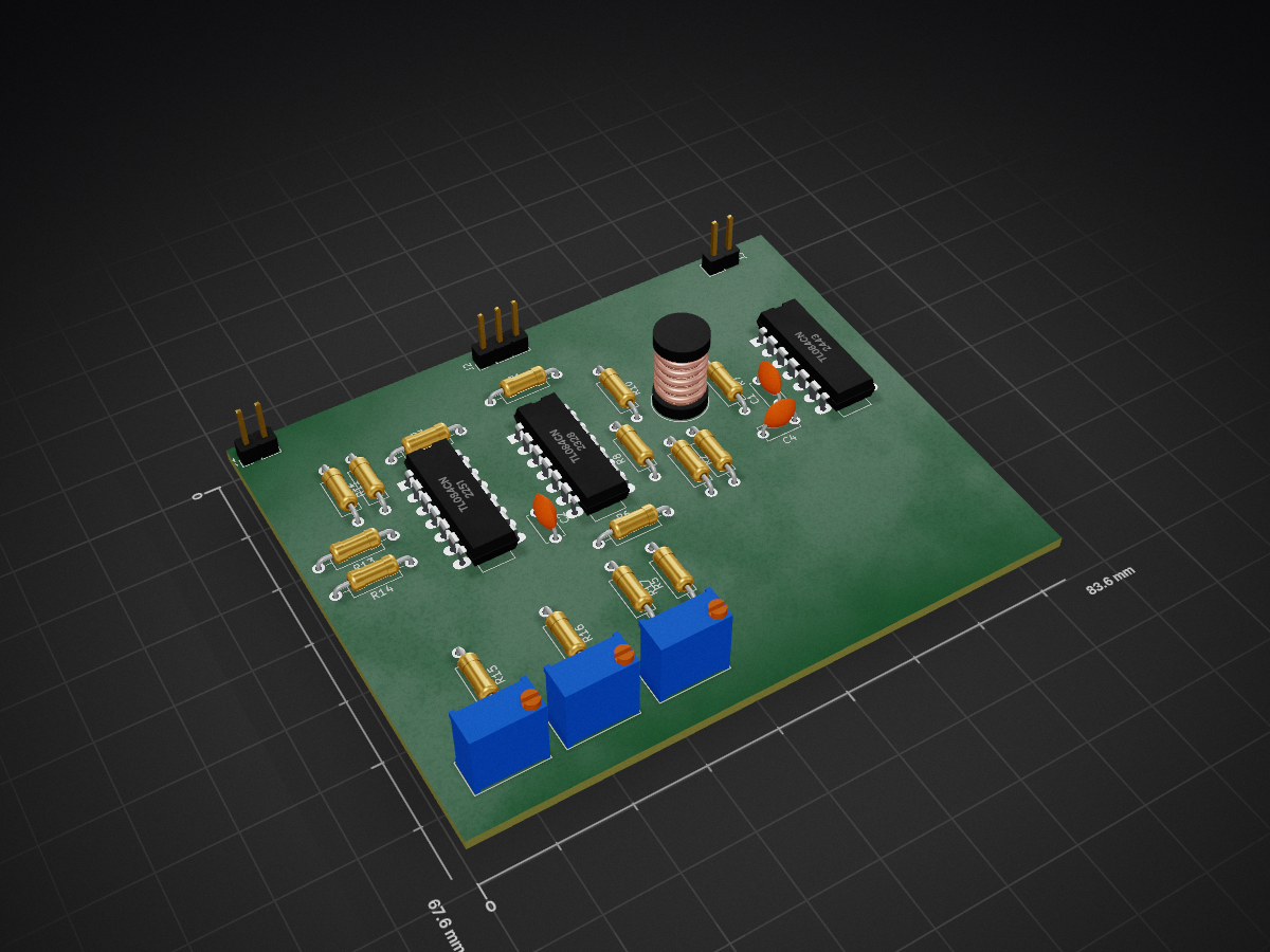
PID RLC is an open-source printed circuit board by UAA-F14, from the UAA-F14/PID-RLC repository on GitHub. It is a 2-layer board of 83.6 × 67.6 mm with 30 parts on 28 nets, routed with 221 tracks and 0 vias.
It is built around the TL084CN. Its parts include 16 resistors, 4 capacitors, 3 ICs, 3 connectors and 1 inductor.
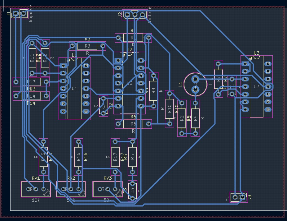
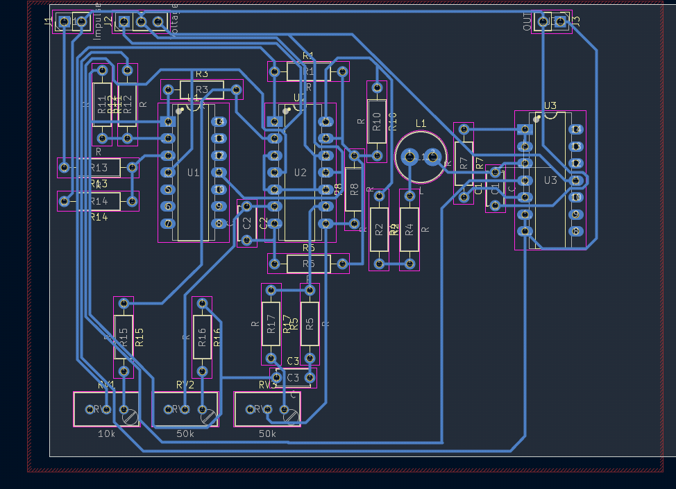
| Qty | Value | Footprint | References |
|---|---|---|---|
| 16 | R | Resistor_THT:R_Axial_DIN0207_L6.3mm_D2.5mm_P10.16mm_Horizontal | R1, R2, R3, R4, R5, R6, R7, R8, R10, R11, R12, R13, R14, R15, R16, R17 |
| 4 | C | Capacitor_THT:C_Disc_D5.0mm_W2.5mm_P5.00mm | C1, C2, C3, C4 |
| 3 | TL084CN | PCM_Package_DIP_AKL:DIP-14_W7.62mm_LongPads | U1, U2, U3 |
| 2 | 50k | Potentiometer_THT:Potentiometer_Bourns_3296W_Vertical | RV2, RV3 |
| 1 | 10k | Potentiometer_THT:Potentiometer_Bourns_3296W_Vertical | RV1 |
| 1 | Impulse | Connector_PinHeader_2.54mm:PinHeader_1x02_P2.54mm_Vertical | J1 |
| 1 | L | Inductor_THT:L_Radial_D7.5mm_P3.50mm_Fastron_07P | L1 |
| 1 | OUT | Connector_PinHeader_2.54mm:PinHeader_1x02_P2.54mm_Vertical | J3 |
| 1 | Voltage | Connector_PinHeader_2.54mm:PinHeader_1x03_P2.54mm_Vertical | J2 |


dustpot/electronic-test-bench
A Raspberry Pi 4 bench instrument featuring a function generator, ohmmeter, voltmeter, DC voltage reference, and frequency meter, all controlled with a rotary encoder and a 20×4 LCD.

EzeCombina/Sumo
2023: Segunda versión del robot ---> MEGAPODA - Hecho con SolidWorks 2020 -

google/mozc-devices
Circuit diagrams and firmware source code for Gboard DIY keyboards

It measures 83.6 × 67.6 mm and has 2 copper layers, 1.6 mm thick.
30 parts, built around the TL084CN. The full list of its parts is on this page, with links to each part's symbol and footprint where PCBKit's library has them.
From the UAA-F14/PID-RLC repository on GitHub, at the commit this page was made from: the board is design/design/design.kicad_pcb and its schematic design/design/design.kicad_sch. PCBKit opens the board in the browser, with nothing to install.
Its repository states no licence, so its author keeps all rights: ask UAA-F14 before reusing the design.