
2 layers20.3 × 62 mm

 TuDo-Makerspace/MIDI-Breakouts6
Just another pair of MIDI breakouts
MIDI OUT is an open-source printed circuit board by TuDo-Makerspace, from the TuDo-Makerspace/MIDI-Breakouts repository on GitHub. It is a 2-layer board of 20.3 × 50.9 mm with 15 parts on 14 nets, routed with 49 tracks and 0 vias.
It is built around the BS170. Its parts include 6 resistors, 2 transistors, 2 connectors and 1 switch. It belongs with the audio and music and interfaces and adapters boards of this library.
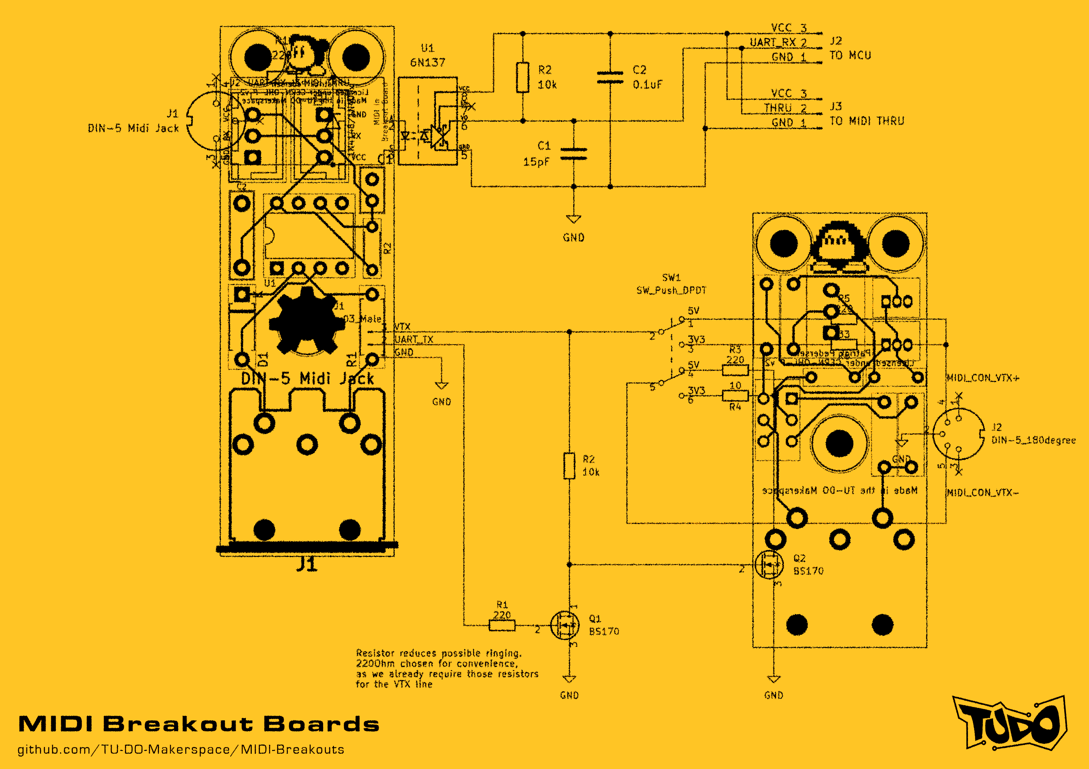
This repository contains the KiCad files for a pair of MIDI breakout boards. There isn't anything particularly special about them, besides perhaps the fact that the MIDI OUT has a switch to select between 3.3V and 5V operation, as well as two BS170 MOSFETs to sink the current, rather than using buffer chips. Oh, and we use JST-XH connectors, because I hate those loose "DuPont" headers that allow you to plug things in the wrong way around! >:(
Further, one may also question the odd choice of some components, such as the 100nF film capacitor for voltage decoupling, instead of a 100nF ceramic capacitor. This really leads us to why these boards have even been made in first place. They were really just intended as test boards to try out some template MIDI schematics I designed for future projects that require MIDI support. The components were chosen according to the stuff we had lying around in our lab, hence the quirky choice of components and varying resistor footprints.
I'm still dumping this on GitHub, as we still have a few of these boards lying around and the repo serves as good documentation, but perhaps someone out there might also find them useful. After all, if you don't feel like using pricey film caps, you can always just pop in a ceramic one instead! The footprint is not that different!
MIDI IN:
MIDI OUT:
Both boards are compliant with the MIDI Specification
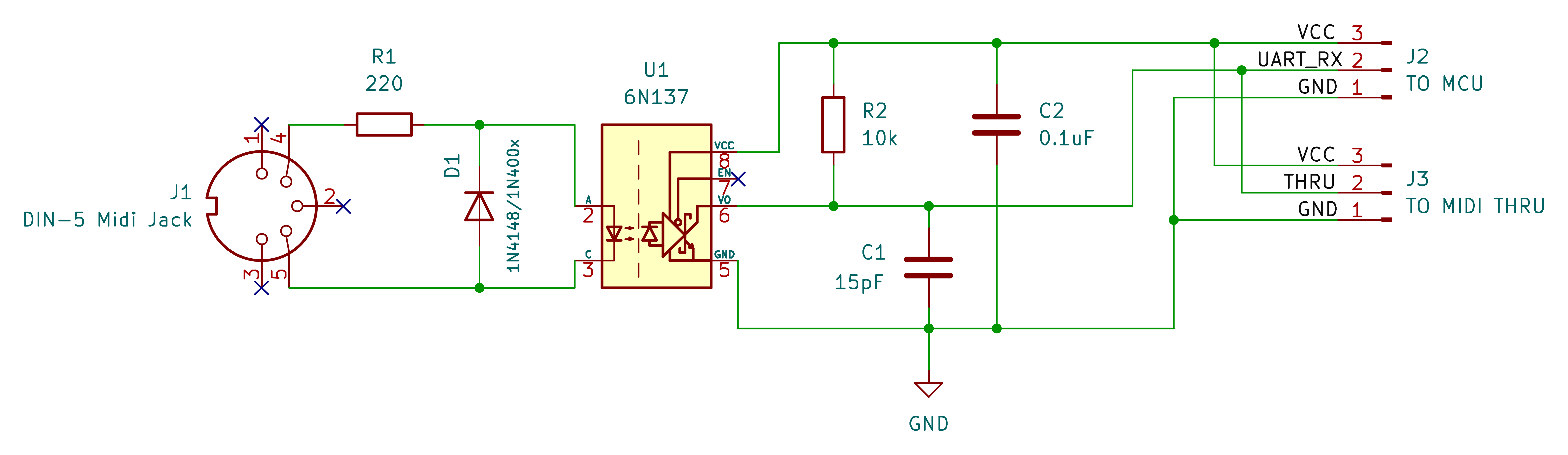
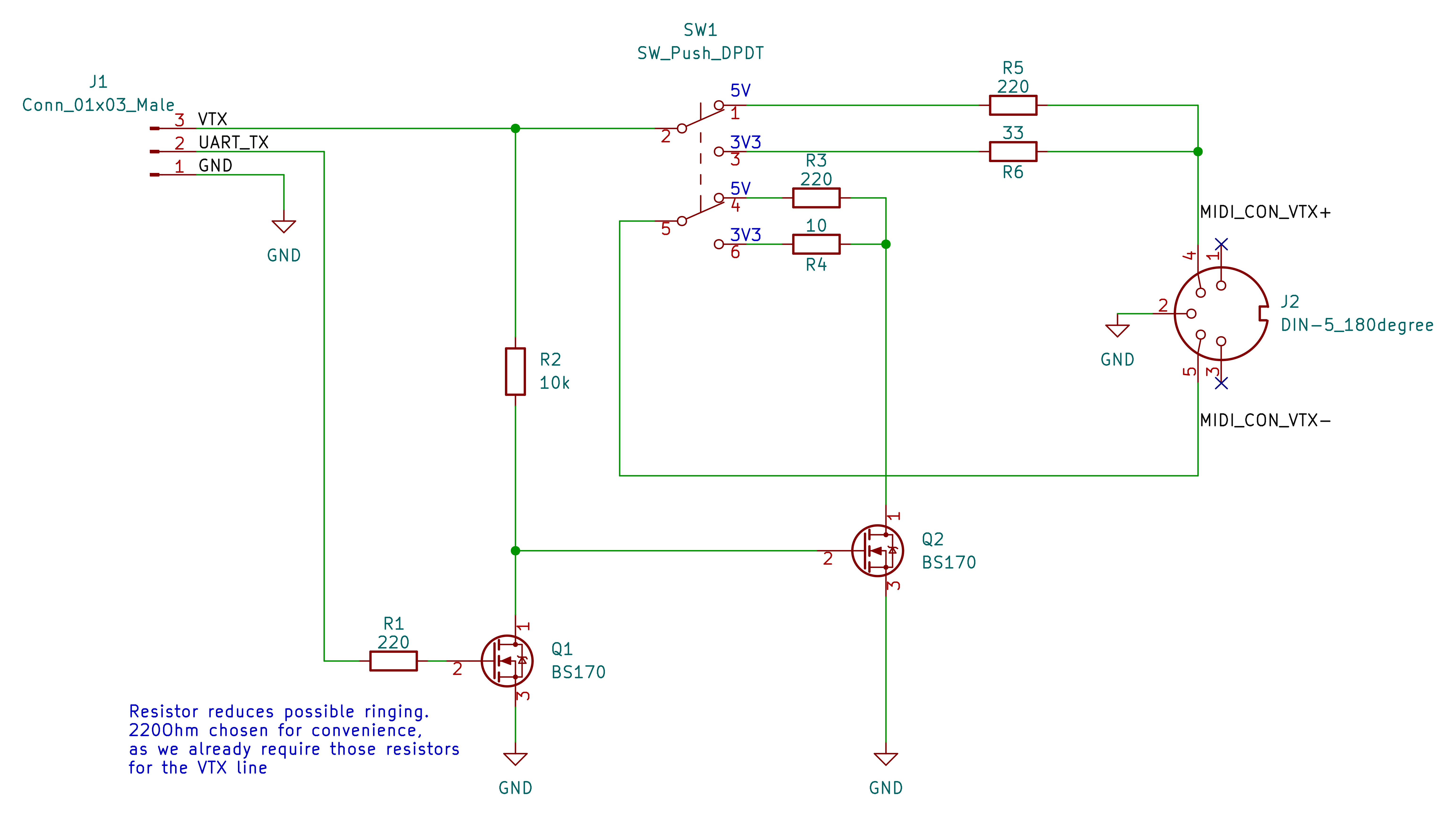
The directories for the individual boards contain a "Gerbers" directory, which contains the gerber files for the respective board. You can use these to order the boards from your desired PCB manufacturer.
An interactive BOM for both boards can be found here
The interactive bom contains a PCB view that allows you to see which components go where, and what value they have. This is particularly useful to have open while assembling the boards.
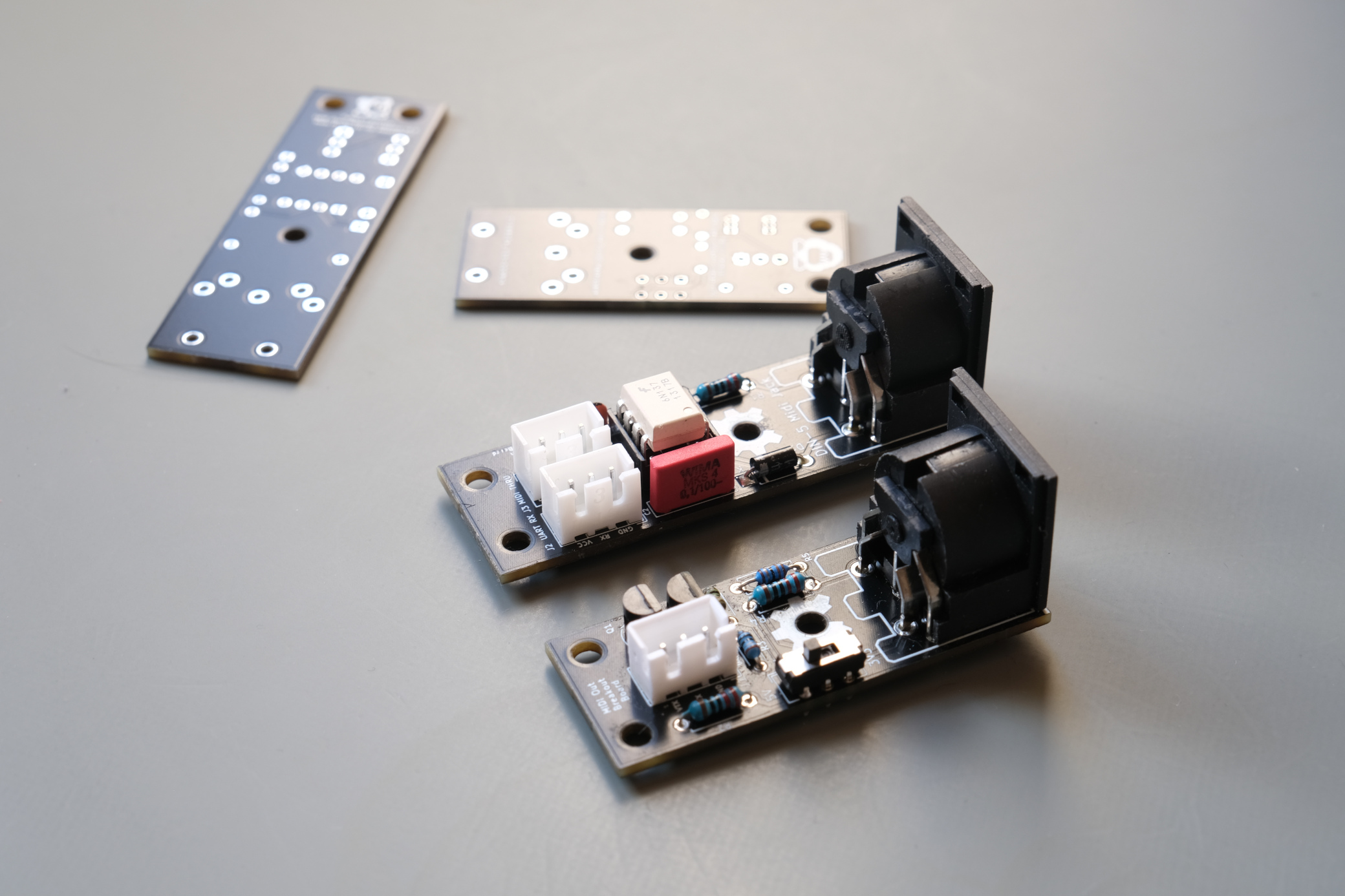
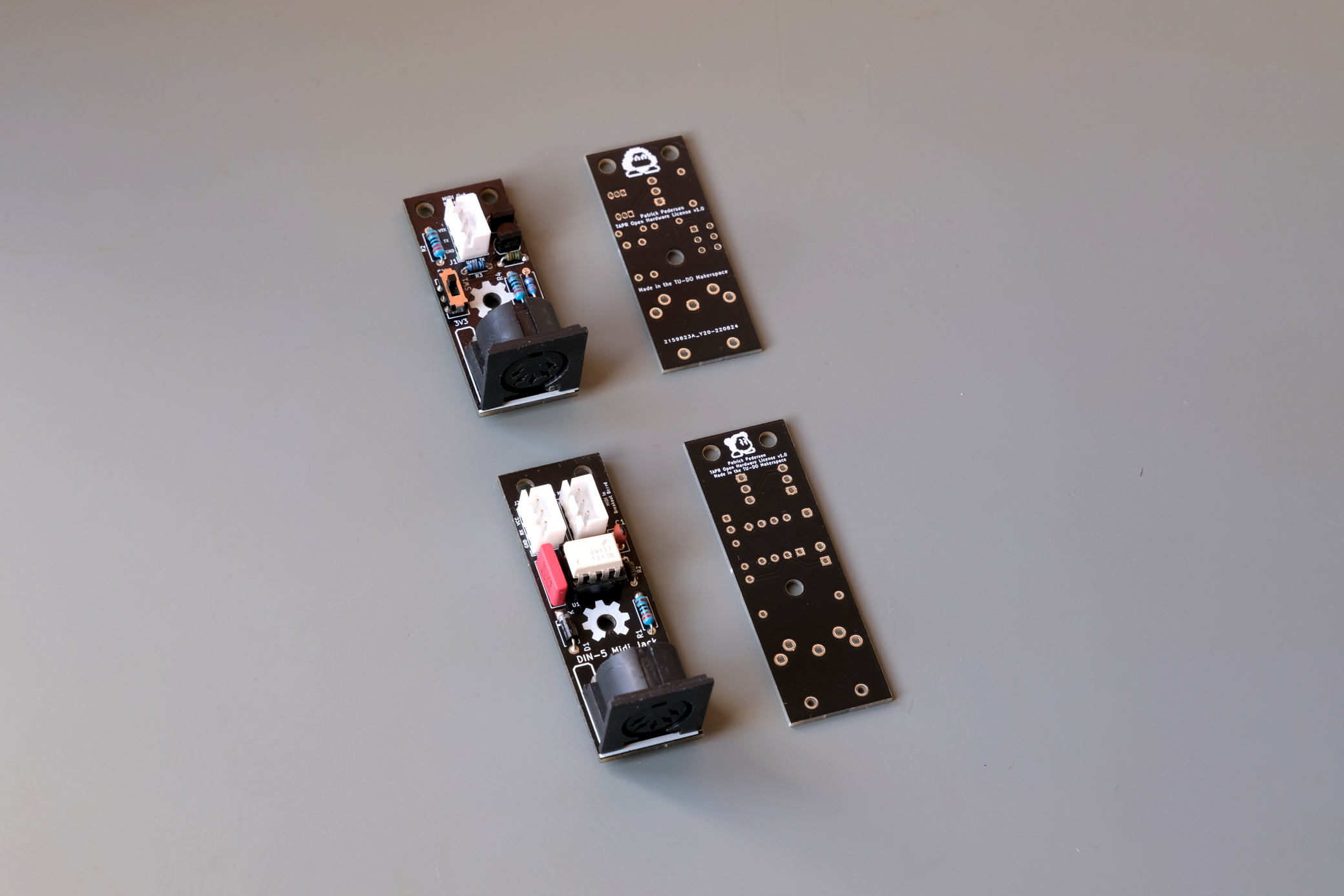
The following project is licensed under the CERN-OHL-P v2 license
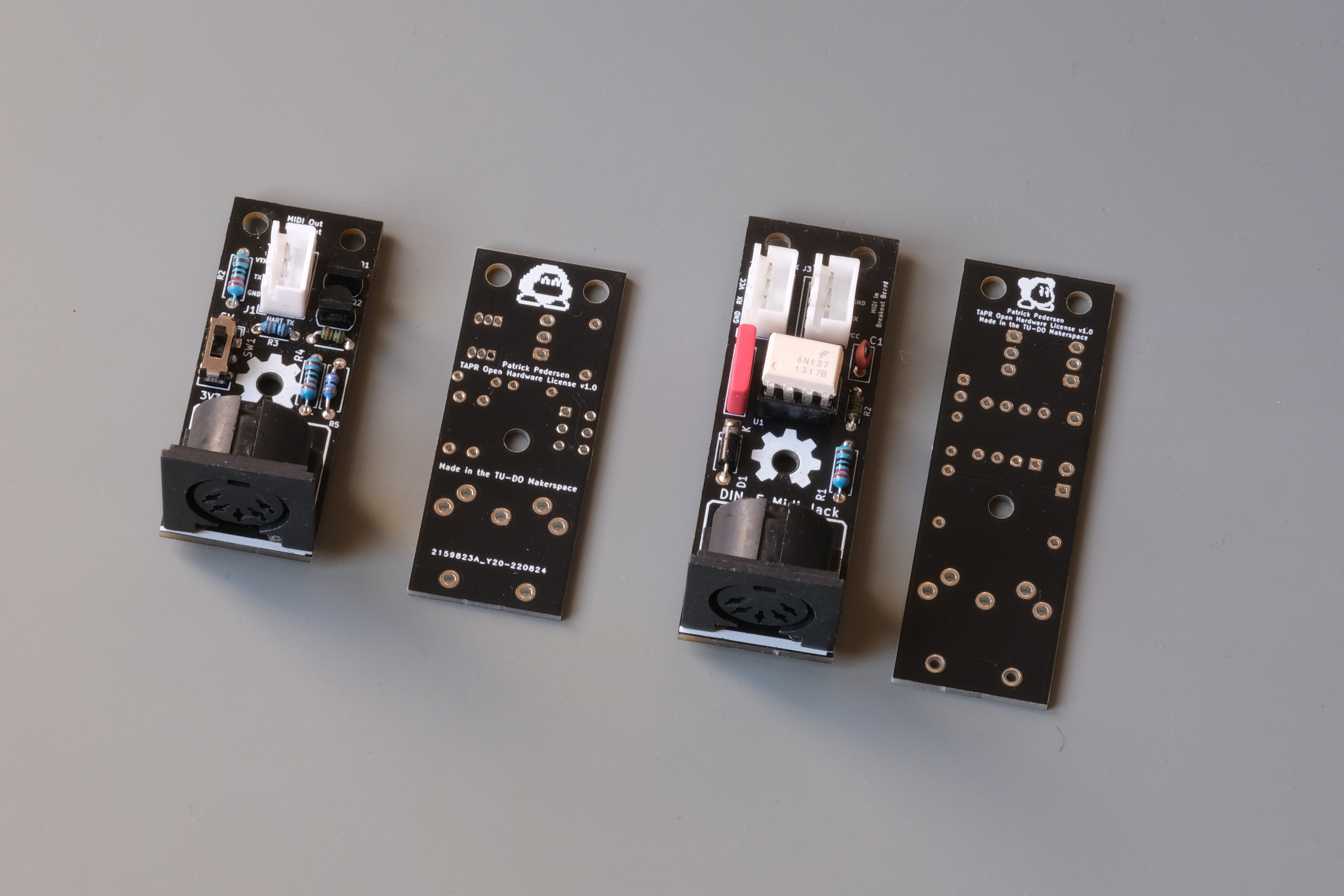
The boards on the pictures claim TAPR Open Hardware License v1.0, however, the KiCAD project has been updated to use the CERN-OHL-P v2 license.
Crediting is always appreciated, even for something as trivial as a pair of breakout boards!
| Qty | Value | Footprint | References |
|---|---|---|---|
| 3 | 220 | Resistor_THT:R_Axial_DIN0207_L6.3mm_D2.5mm_P7.62mm_Horizontal | R1, R3, R5 |
| 2 | BS170 | Package_TO_SOT_THT:TO-92L_Inline | Q1, Q2 |
| 1 | 10 | Resistor_THT:R_Axial_DIN0204_L3.6mm_D1.6mm_P5.08mm_Horizontal | R4 |
| 1 | 10k | Resistor_THT:R_Axial_DIN0204_L3.6mm_D1.6mm_P5.08mm_Horizontal | R2 |
| 1 | 33 | Resistor_THT:R_Axial_DIN0207_L6.3mm_D2.5mm_P7.62mm_Horizontal | R6 |
| 1 | Conn_01x03_Male | Connector_JST:JST_XH_B3B-XH-A_1x03_P2.50mm_Vertical | J1 |
| 1 | DIN-5_180degree | Eurocad:MIDI_DIN5 | J2 |
| 1 | SW_Push_DPDT | Button_Switch_THT:SW_CuK_JS202011CQN_DPDT_Straight | SW1 |
The 11 most common of 15 parts.


pablozg/freeds
Derivador de energía solar excedente creado por Pablo Zerón, Diseño PCB por Amcalo, Tester original por Aeizoon, Wiki por Zoilo Mora

PhysicsDptAngers/polyUAnalog
Open source, analog and polyphonic synthesizer


DRWJSCHMIDT/T41
This is the repository for the officially released V10, V11, and V12 versions of the T41 Software Defined Transceiver hardware and kits.

sffubs/dactyl_manuform_gimbal
Instrutions and designs for building the dactyl-manuform-gimbal keyboard
It measures 20.3 × 50.9 mm and has 2 copper layers, 1.6 mm thick.
15 parts, built around the BS170. The full list of its parts is on this page, with links to each part's symbol and footprint where PCBKit's library has them.
From the TuDo-Makerspace/MIDI-Breakouts repository on GitHub, at the commit this page was made from: the board is MIDI_OUT/MIDI_OUT.kicad_pcb and its schematic MIDI_IN/MIDI_IN.kicad_sch. PCBKit opens the board in the browser, with nothing to install.
Its repository states no licence, so its author keeps all rights: ask TuDo-Makerspace before reusing the design.