2 layers57.3 × 19 mm

 Trirosmos/pico_gg_lcd21
Open source Game Gear replacement screen mod based on the RP2040.
GG LCD DIY is an open-source printed circuit board by Trirosmos, from the Trirosmos/pico_gg_lcd repository on GitHub, published under the MIT licence. It is a 2-layer board of 97.3 × 59 mm with 26 parts on 67 nets, routed with 328 tracks and 32 vias.
Its parts include 16 connectors, 3 capacitors, 2 resistors, 2 diodes and 1 IC. It belongs with the lEDs and displays boards of this library.
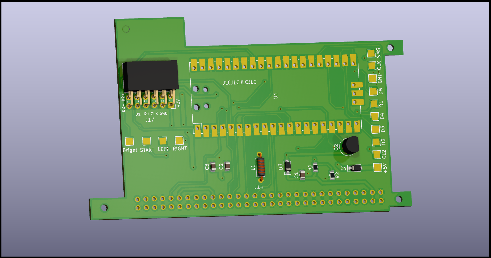
RP2040-based Game Gear screen replacement kit. Even a cheapo modern LCD has much, much, much better contrast ratio than the OG screen.
Clone this repository and pull all submodules:
git clone https://github.com/Trirosmos/pico_gg_lcd
cd pico_gg_lcd
git submodule update --init --recursive
Then, run sw/build.sh:
cd sw
mkdir build
cd build
cmake ../CMakeLists.txt
make
This should generate an uf2 file you can upload to the RP2040;
Componentes you'll need and their approximate cost:
Total approximate BOM cost: $26
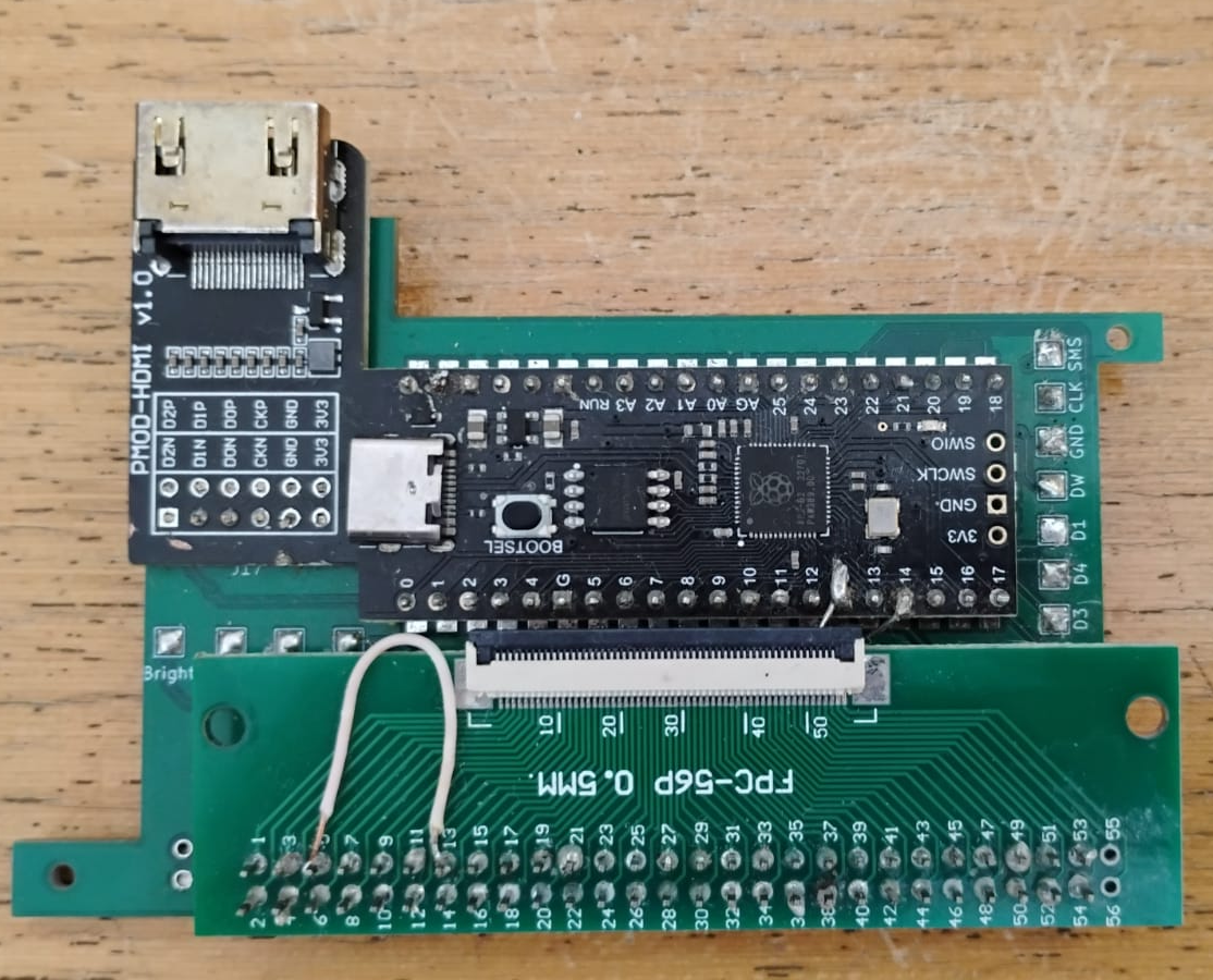
First assemble passive components and transistor, then the RP2040 board and leave the FPC connector to be connected last. The final board should look something like this, sans the bodge wire:
The Game Gear ASIC generates digital video signals that the LCD drivers in the LCD ribbon use to drive the actual display segments.
In NTSC mode, i.e, when test pad T10 is connected to +5V, the timings of the signals from the ASIC closely resemble what one would expect from a console like the Master System. All screen replacement kits run the Game Gear in this mode, as far as I'm aware.
The communication protocol used between the ASIC and the LCD drivers in this mode is well documented and essentially boils down to:
One of the PIOs is takes alongside three DMA channels with building a live framebuffer in RAM with the image data the GG is sending out.
Three PIO SMs are used in the following manner:
One of the DMA channels then takes the 12bpp pixel data from the PIO RX FIFO and saves it into RAM.
Finally, one of the CPU cores upscales the image and sends it out to the LCD.
| Qty | Value | Footprint | References |
|---|---|---|---|
| 1 | +5V | TestPoint:TestPoint_Pad_2.0x2.0mm | J15 |
| 1 | 100k | Resistor_SMD:R_0805_2012Metric | R1 |
| 1 | 100n | Capacitor_SMD:C_0805_2012Metric | C1 |
| 1 | 100u | Capacitor_SMD:C_0805_2012Metric | C2 |
| 1 | 10k | Resistor_SMD:R_0805_2012Metric | R2 |
| 1 | 22u | Capacitor_SMD:C_0805_2012Metric | C3 |
| 1 | 2N2222 | Package_TO_SOT_THT:TO-92 | Q2 |
| 1 | 470u | Inductor_THT:L_Axial_L5.3mm_D2.2mm_P7.62mm_Horizontal_Vishay_IM-1 | L1 |
| 1 | Bright | TestPoint:TestPoint_Pad_2.0x2.0mm | J1 |
| 1 | CL2 | TestPoint:TestPoint_Pad_2.0x2.0mm | J6 |
| 1 | CLK | TestPoint:TestPoint_Pad_2.0x2.0mm | J8 |
| 1 | ChinaPico | MCU_RaspberryPi_and_Boards:RPi_Pico_SMD_TH | U1 |
| 1 | Conn_01x60 | GG_LCD:FPC_60_Adapter | J14 |
| 1 | Conn_02x06_Odd_Even | Connector_PinSocket_2.54mm:PinSocket_2x06_P2.54mm_Horizontal | J17 |
| 1 | D | Diode_SMD:D_SOD-123 | D3 |
| 1 | D1 | TestPoint:TestPoint_Pad_2.0x2.0mm | J2 |
| 1 | D2 | TestPoint:TestPoint_Pad_2.0x2.0mm | J3 |
| 1 | D3 | TestPoint:TestPoint_Pad_2.0x2.0mm | J4 |
| 1 | D4 | TestPoint:TestPoint_Pad_2.0x2.0mm | J5 |
| 1 | DW | TestPoint:TestPoint_Pad_2.0x2.0mm | J7 |
| 1 | D_Schottky | Diode_SMD:D_SOD-123 | D1 |
| 1 | GND | TestPoint:TestPoint_Pad_2.0x2.0mm | J16 |
| 1 | LEFT | TestPoint:TestPoint_Pad_2.0x2.0mm | J10 |
| 1 | RIGHT | TestPoint:TestPoint_Pad_2.0x2.0mm | J11 |
| 1 | SMS | TestPoint:TestPoint_Pad_2.0x2.0mm | J9 |
| 1 | START | TestPoint:TestPoint_Pad_2.0x2.0mm | J12 |

hackclub/OnBoard
💡 Join 1,000 teenagers and make your first PCB with a $100 grant!


harbaum/galagino
A Galaga, Pac-Man and Donkey Kong arcade emulator for the ESP32

Luos-io/luos_engine
Open-source and real-time orchestrator for cyber-physical-systems, to easily design, test and deploy embedded applications and digital twins.

google/walt
A device for measuring latency of physical sensors and outputs on phones and computers

It measures 97.3 × 59 mm and has 2 copper layers, 1.6 mm thick.
26 parts. The full list of its parts is on this page, with links to each part's symbol and footprint where PCBKit's library has them.
From the Trirosmos/pico_gg_lcd repository on GitHub, at the commit this page was made from: the board is hw/GG_LCD_DIY.kicad_pcb and its schematic hw/GG_LCD_DIY.kicad_sch. PCBKit opens the board in the browser, with nothing to install.
Its repository publishes it under the MIT licence: you may reuse it on that licence's terms (keep the author's notice, and for a copyleft licence share your changes alike).