2 layers161.3 × 181.6 mm
1 - ATX 16 bit ISA passive backplane
FredericSegard/Fr80
Z80 Homebrew computer, code-named Fre80, pronounced Freddy.
94 parts2

 Toysoft/mb386sx-rc2016
The origin of this project is the M396F motherboard replica by Marco Both. Marco replicated the PCB layout of a certain revision of M396F motherboard. He didn't provide the schematic.
AT386SX is an open-source printed circuit board by Toysoft, from the Toysoft/mb386sx-rc2016 repository on GitHub. It is a 2-layer board of 172.7 × 218.4 mm with 150 parts on 309 nets, routed with 8,868 tracks and 700 vias.
It is built around the 74HC05D, 74HCT14D and 74HCT74D, with the DS12885N+, LM7905T and CR2032 among its other parts. Its parts include 48 capacitors, 40 resistors, 17 connectors, 10 ICs and 4 inductors.


An 386SX/486SLC Motherboard based on SARC RC2016 Chipset
The origin of this project is the M396F motherboard replica by Marco Both. Marco replicated the PCB layout of a certain revision of M396F motherboard. He didn't provide the schematic.
I reverse engineered the schematic based on his PCB layout and made a PCB layout using that schematic similar to the Marco's replica. This was the initial version of this project - version 1.0.
The subsequent versions contain the following improvements:
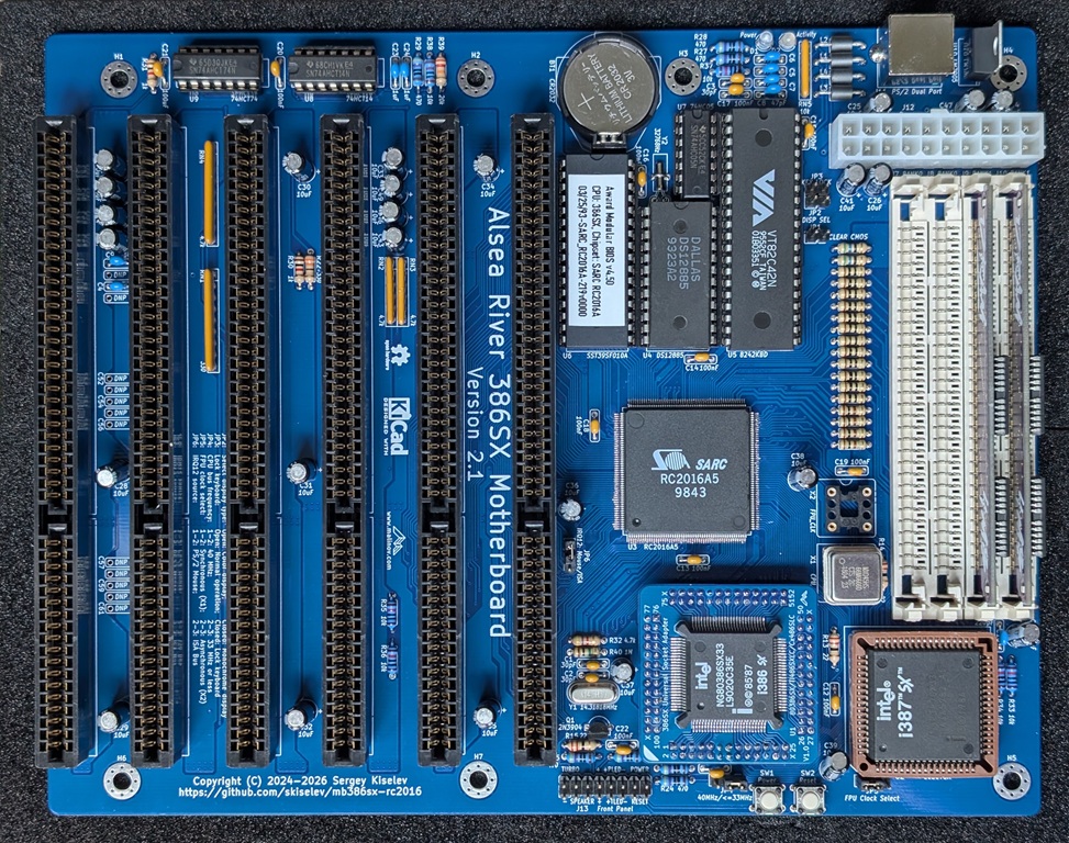
Alsea River 386SX Motherboard project on Mouser.com - View and order most components except of the CPU, chipset, keyboard controller, SIMM-30 sockets, and the PCB.
| Component type | Reference | Description | Quantity | Possible sources and notes |
|---|---|---|---|---|
| PCB | Alsea River 386SX PCB - Version 2.1 | 1 | Order from a PCB manufacturer of your choice using provided Gerber or KiCad files | |
| Integrated Circuit | U1 | 386SX CPU, TI486SXLC, Cx486SLC CPU, 100 pin BQFP | 1 | eBay |
| Integrated Circuit | U2 | 387SX FPU or compatible, 68 pin PLCC | 1 | eBay. Optional |
| Integrated Circuit | U3 | SARC RC2016A5, 208 pin PQFP | 1 | UTsource |
| Integrated Circuit | U4 | DS12885 RTC, 24 pin DIP | 1 | Mouser 700-DS12885 |
| Integrated Circuit | U5 | VT82C42N keyboard/mouse controller, 40 pin DIP | 1 | eBay |
| Integrated Circuit | U6 | SST39SF010A 128 KiB Flash ROM, 32 pin DIP | 1 | Mouser 804-39SF010A7CPHE |
| Integrated Circuit | U7 | 74HC05 inverters with open drain outputs, 14 pin DIP | 1 | Mouser 595-SN74AHC05N, 595-SN74HC05N, 595-SN74LS06N |
| Integrated Circuit | U8 | 74HCT14 inverters with Schmitt trigger inputs, 14 pin DIP | 1 | Mouser 595-SN74AHCT14N, 595-SN74HCT14N |
| Integrated Circuit | U9 | 74HCT74 D-flip flops, 14 pin DIP | 1 | Mouser 595-SN74AHCT74N, 595-SN74HCT74N, |
| Integrated Circuit | U10 | LM7905 -5V voltage regulator, TO-220-3 | 1 | Mouser 863-MC7905CTG, 926-LM7905CT/NOPB |
| Transistor | Q1 | 2N3904, NPN transistor, TO-92 | 1 | Mouser 512-2N3904TA |
| LED | D1 | 3 mm LED, blue | 1 | Optional. Mouser 604-WP710A10QBD/D, 696-SSL-LX3054USBD, 749-3BWD-S |
| LED | D2 | 3 mm LED, bi-color red/green | 1 | Optional. Mouser 604-WP937EGW, 696-SSL-LX3054IGW, 749-3BC |
| LED Spacer | D1, D2 | Spacer for 3 mm LEDs, 3mm height | 2 | Optional. Mouser 749-ELM-2-3MM |
| Crystal Oscillator | X1 | 66 MHz (twice desired CPU frequency), 5V, DIP-8 | 1 | Mouser 50 MHz: 520-TCH5000, 815-ACH-50-EK, 774-MXO45HS-3C-50.0; 66.6666MHz: 774-MXO45HS2C66.6666, 520-TCH6666-X; 80 MHz: 520-ECS-2200B-800, 774-MXO45HS-3C-80.0 |
| Crystal Oscillator | X2 | 66 MHz (twice desired FPU frequency), 5V, DIP-8 | 1 | Optional. See above. |
| Crystal Resonator | Y1 | 14.31818 MHz, parallel, HC-49U | 1 | Mouser 815-ABL-14.31818B2, 559-FOXS143-20-LF |
| Crystal Resonator Insulator | Y1 | Mylar insulator for HC-49U crystal resonators | 1 | Optional. Mouser 749-CI-192-028-SR |
| Crystal Resonator | Y2 | 32768 Hz, watch crystal, 6 pf, D = 2.1 mm, L = 6.2 mm | 1 | Mouser 815-AB26T32768KHZ6B, 520-ECS327-6-13-X, or 628-VT200F-6PF20PPM |
| IC Socket | U2 | 68 pin PLCC, through hole | 1 | Mouser 737-PLCC-68-AT, 517-8468-11B1-RK-TP, 575-682444 |
| IC Socket | U4 | 24 pin DIP | 1 | Mouser 737-ICS-624-T, 517-4824-6000-CP, 571-1-2199298-8 |
| IC Socket | U5 | 40 pin DIP | 1 | Mouser 737-ICS-640-T, 517-4840-6000-CP, 571-1-2199299-5 |
| IC Socket | U6 | 32 pin DIP | 1 | Mouser 737-ICS-632-T, 517-4832-6000-CP, 571-1-2199300-2 |
| IC Socket | U7 - U9 | 14 pin DIP | 3 | Mouser 737-ICS-314-T, 517-4814-3000-CP, 571-1-2199298-3 |
| Oscillator Socket | X1, X2 | 4 pin DIP | 2 | Mouser 535-1108800 |
| Battery | BT1 | CR2032 battery | 1 | Mouser 81-CR2032, 658-CR2032, 614-CR2032-200 |
| Battery Socket | BT1 | CR2032 battery socket, through hole | 1 | Mouser 122-2420-GR, 122-2620-GR |
| Connector | J1 - J4 | SIMM 30 socket, 30 pin | 4 | eBay |
| Connector | J5 - J10 | ISA card edge connector, 98 pin | 6 | Mouser 587-395-098-520-350 |
| Connector | J11 | PS/2 Keyboard/Mouse connector, Mini-DIN 6 pin | 1 | Mouser 806-KMDGX-6S-BS |
| Connector | J12 | ATX power connector, 20 pin | 1 | Mouser 538-46015-2006 |
| Connector | J13 | 2x8 pin header, 2.54 mm (0.1") pitch, through hole | 1 | Mouser 737-PH2-16-UA |
| Connector | J14 - J17 | 2x14 pin socket, 2 mm pitch, through hole | 4 | Optional. Mouser 538-79107-7062, 200-SQT11301LD, 200-SQT11301FD |
| Connector | JP1 - JP3 | 2 pin header, 2.54 mm (0.1") pitch, through hole | 3 | Mouser 737-PH1-02-UA |
| Connector | JP4 - JP6 | 3 pin header, 2.54 mm (0.1") pitch, through hole | 3 | Mouser 737-PH1-03-UA. Some headers are optional, and can be hardwired for the soldered CPU. |
| Connector | JP1 - JP6 | Shunt, 2 pin, 2.54 mm (0.1") pitch | 4 | Mouser 737-MSA-G, 806-SX1100-B |
| Switch | SW1, SW2 | 6 mm tactile switch, vertical, through hole | 2 | Optional. Mouser 653-B3F-1000 |
| Capacitor | C1 - C3 | 30 pF, 50V MLCC, 5.08 mm (0.2") pitch | 3 | Mouser 594-K300J10C0GF5UH5 |
| Capacitor | C4 - C7 | 47 pF, 50V MLCC, 5.08 mm (0.2") pitch | 4 | Mouser 810-FG28C0G1H470JNT6 |
| Capacitor | C8 | 100 pF, 50V MLCC, 5.08 mm (0.2") pitch | 1 | Mouser 810-FG28C0G1H101JNT6 |
| Capacitor | C9 | 220 pF, 50V MLCC, 5.08 mm (0.2") pitch | 1 | Mouser 810-FG28C0G1H221JNT6 |
| Capacitor | C10 - C21 | 100 nF, 25V MLCC, 5.08 mm (0.2") pitch | 12 | Mouser 594-K104K15X7RF53H5, 810-FG28X7R1H104KNT6 |
| Capacitor | C22, C23 | 1 uF, 10V MLCC, 5.08 mm (0.2") pitch | 2 | Mouser 810-FG28X5R1H105KRT6 |
| Capacitor | C24 - C48 | 10 uF, 25V electrolytic, 5 mm diameter, 2.5 mm pitch | 25 | Mouser 667-EEU-FR1H100 |
| Polyfuse | F1 | 1.1A, 5.08 mm (0.2") pitch | 1 | Mouser 650-RUSBF110-2 |
| Ferrite Choke | L1 - L4 | axial | 4 | Mouser 623-2743001112LF |
| Resistor | R1 - R12 | 10 ohm, 0.25 W, axial | 12 | Mouser 708-CF14JT10R0, 603-MFR-25FBF52-10R |
| Resistor | R13 - R15 | 22 ohm, 0.25 W, axial | 3 | Mouser 708-CF14JT22R0, 603-MFR-25FBF52-22R |
| Resistor | R16, R17 | 56 ohm, 0.25 W, axial | 2 | Mouser 708-CF14JT56R0, 603-MFR-25FBF52-56R |
| Resistor | R18 - R21 | 100 ohm, 0.25 W, axial | 4 | Mouser 708-CF14JT100R, 603-MFR-25FBF52-100R |
| Resistor | R22 | 330 ohm, 0.25 W, axial | 1 | Mouser 708-CF14JT330R, 603-MFR-25FBF52-330R |
| Resistor | R23 - R29 | 470 ohm, 0.25 W, axial | 7 | Mouser 708-CF14JT470R, 603-MFR-25FBF52-470R |
| Resistor | R30, R31 | 1 kohm, 0.25 W, axial | 2 | Mouser 708-CF14JT1K00, 603-MFR-25FBF52-1K |
| Resistor | R32 | 4.7 kohm, 0.25 W, axial | 1 | Mouser 708-CF14JT4K70, 603-MFR-25FBF52-4K7 |
| Resistor | R33 - R38 | 10 kohm, 0.25 W, axial | 6 | Mouser 708-CF14JT10K0, 603-MFR-25FBF52-10K |
| Resistor | R39 | 22 kohm, 0.25 W, axial | 1 | Mouser 708-CF14JT22K0, 603-MFR-25FBF52-22K |
| Resistor | R40 | 1 Mohm, 0.25 W, axial | 1 | Mouser 708-CF14JT1M00, 603-MFR-25FBF52-1M |
| Resistor Array | RN1 | 330 ohm, 8 resistors, bussed, 9 pin SIL | 1 | Mouser 652-4609X-1LF-330, 652-4609X-AP1-331LF |
| Resistor Array | RN2, RN3 | 4.7 kohm, 5 resistors, bussed, 6 pin SIL | 2 | Mouser 652-4606X-1LF-4.7K, 652-4606X-AP1-472LF |
| Resistor Array | RN4 | 4.7 kohm, 8 resistors, bussed, 9 pin SIL | 1 | Mouser 652-4609X-1LF-4.7K, 652-4609X-AP1-472LF |
| Resistor Array | RN5 | 10 kohm, 4 resistors, bussed, 5 pin SIL | 1 | Mouser 652-4605X-1LF-10K, 652-4605X-AP1-103LF |
For the testing purposes I am using BIOSes from other commerical motherboards based on the same SARC RC2016 chipset. The Retro Web has a collection of the BIOSes for this chipset.
The is designed for the 128 KiB SST SST39SF010A Flash ROM. This ROM is mapped to the 0xE0000-0xFFFFF (or, with 8086 segments, E000:0000 to F000:FFFF). The upper 64 KiB - 0xF0000-0xFFFFF (F000:0000-F000:FFFF) are typically used for the BIOS ROM. The lower 64 KiB - 0xE0000-0xEFFFF can be used for BIOS extensions. Please take that into the consideration when programming the Flash ROM. Make sure to load the BIOS image to the top 64 KiB of the Flash ROM, starting at the address 0x10000. Other pin compatible 128 KiB Flash ROMs, such as AMD AM29F010A, SST SST29EE010, Atmel AT29C010A can be also used without any changes.
It is also possible to use 256 KiB and 512 KiB Flash ROMs, for example SST39SF020 and SST39SF040. Note that the A17 address line is connected to VCC (logic high/"1") and the address line A18 is connected to the ground (logic low/"0"). Therefore when using these flash ROMs, please program the 64 KiB BIOS image starting at the addres 0x30000 of the Flash ROM.
Finally, the board also should work with 64 KiB EPROMs and OTP ROMs, e.g., 27C512. In this case, install the EPROM to the right side of the socket, that is pin 1 of the EPROM should go to the pin 3 of the socket.
Version 2.3
Version 2.2
Version 2.1
Version 2.0
Version 1.9
Version 1.8
Version 1.7
Version 1.6
Version 1.5
Version 1.4
Version 1.3
Version 1.2
Version 1.1
Version 1.0
Versions 1.8 - 2.1
Versions 1.0 - 2.1
| Qty | Value | Footprint | References |
|---|---|---|---|
| 25 | 10uF | My_Components:Cap_Elec_Radial_5mm_2.5mm | C24, C25, C26, C27, C28, C29, C30, C31, C32, C33, C34, C35, C36, C37, C38, C39 +9 |
| 12 | 10 | My_Components:Res_762 | R1, R2, R3, R4, R5, R6, R7, R8, R9, R10, R11, R12 |
| 12 | 100nF | My_Components:Cap_Cer_508 | C10, C11, C12, C13, C14, C15, C16, C17, C18, C19, C20, C21 |
| 7 | 470 | My_Components:Res_762 | R23, R24, R25, R26, R27, R28, R29 |
| 7 | HOLE | MountingHole:MountingHole_4mm_Pad_Via | H1, H2, H3, H4, H5, H6, H7 |
| 6 | 10k | My_Components:Res_762 | R33, R34, R35, R36, R37, R38 |
| 6 | BUSAT_HOST | My_Components:Conn_Edge_ISA16 | J5, J6, J7, J8, J9, J10 |
| 4 | 100 | My_Components:Res_762 | R18, R19, R20, R21 |
| 4 | 47pF | My_Components:Cap_Cer_508 | C4, C5, C6, C7 |
| 4 | Ferrite | My_Components:L_Ferrite_1016 | L1, L2, L3, L4 |
| 3 | 22 | My_Components:Res_762 | R13, R14, R15 |
| 3 | 30pF | My_Components:Cap_Cer_508 | C1, C2, C3 |
| 2 | 1k | My_Components:Res_762 | R30, R31 |
| 2 | 1uF | My_Components:Cap_Cer_508 | C22, C23 |
| 2 | 4.7k | My_Components:Conn_SIL6 | RN2, RN3 |
| 2 | 56 | My_Components:Res_762 | R16, R17 |
| 2 | BANK0 | My_Components:Conn_SIMM30 | J1, J2 |
| 2 | BANK1 | My_Components:Conn_SIMM30 | J3, J4 |
| 1 | 1.1A | My_Components:Cap_Cer_508 | F1 |
| 1 | 100pF | My_Components:Cap_Cer_508 | C8 |
| 1 | 10k | My_Components:Conn_SIL5 | RN5 |
| 1 | 14.31818MHz | My_Components:Crystal_HC-49U_Vert | Y1 |
| 1 | 1M | My_Components:Res_762 | R40 |
| 1 | 220pF | My_Components:Cap_Cer_508 | C9 |
| 1 | 22k | My_Components:Res_762 | R39 |
| 1 | 2N3904 | My_Components:Transistor_TO92_EBC_254 | Q1 |
| 1 | 32768Hz | My_Components:Crystal_32K_Horiz | Y2 |
| 1 | 330 | My_Components:Res_762 | R22 |
| 1 | 330 | My_Components:Conn_SIL9 | RN1 |
| 1 | 4.7k | My_Components:Res_762 | R32 |
| 1 | 4.7k | My_Components:Conn_SIL9 | RN4 |
| 1 | 40MHz/<=33MHz | My_Components:Conn_Pin_Header_3x1_2.54mm | JP4 |
| 1 | 74HC05 | My_Components:IC_DIP14_300 | U7 |
| 1 | 74HCT14 | My_Components:IC_DIP14_300 | U8 |
| 1 | 74HCT74 | My_Components:IC_DIP14_300 | U9 |
| 1 | 80386SX | My_Components:PQFP-100_19x19mm_P0.635mm_i386sx | U1 |
| 1 | 80387SX | My_Components:IC_PLCC68_INTEL_TH | U2 |
| 1 | 8242KBD | My_Components:IC_DIP40_600 | U5 |
| 1 | Activity | My_Components:LED_3mm | D2 |
| 1 | CLEAR CMOS | My_Components:Conn_Pin_Header_2x1_2.54mm | JP1 |
| 1 | CPU 1-25 | Connector_PinHeader_2.00mm:PinHeader_2x13_P2.00mm_Vertical | J14 |
| 1 | CPU 26-50 | Connector_PinHeader_2.00mm:PinHeader_2x13_P2.00mm_Vertical | J15 |
| 1 | CPU 51-75 | Connector_PinHeader_2.00mm:PinHeader_2x13_P2.00mm_Vertical | J16 |
| 1 | CPU 76-100 | Connector_PinHeader_2.00mm:PinHeader_2x13_P2.00mm_Vertical | J17 |
| 1 | CPU_CLK | My_Components:OSC_Half_Can_DIP8 | X1 |
| 1 | CR2032 | My_Components:Battery_Holder_CR2032_Universal | BT1 |
| 1 | DISP SEL | My_Components:Conn_Pin_Header_2x1_2.54mm | JP2 |
| 1 | DS12885 | My_Components:IC_DIP24_600 | U4 |
| 1 | FPU Clock Select | My_Components:Conn_Pin_Header_3x1_2.54mm | JP5 |
| 1 | FPU_CLK | My_Components:OSC_Half_Can_DIP8 | X2 |
| 1 | Front Panel | My_Components:Conn_Pin_Header_8x2_2.54mm | J13 |
| 1 | IRQ12: Mouse/ISA | My_Components:Conn_Pin_Header_3x1_2.54mm | JP6 |
| 1 | KEY LOCK | My_Components:Conn_Pin_Header_2x1_2.54mm | JP3 |
| 1 | LM7905 | My_Components:IC_TO220-3_Vert | U10 |
| 1 | Logo_Open_Hardware_Small | Symbol:KiCad-Logo2_5mm_SilkScreen | LOGO2 |
| 1 | Logo_Open_Hardware_Small | Symbol:OSHW-Logo2_7.3x6mm_SilkScreen | LOGO1 |
| 1 | PS/2 Dual Port | My_Components:Conn_Mini_DIN_6pin | J11 |
| 1 | Power | My_Components:Switch_Tactile_6mm | SW1 |
| 1 | Power | My_Components:LED_3mm | D1 |
| 1 | Power | My_Components:Conn_Power_ATX_20pin | J12 |
| 1 | RC2016A5 | Package_QFP:PQFP-208_28x28mm_P0.5mm | U3 |
| 1 | Reset | My_Components:Switch_Tactile_6mm | SW2 |
| 1 | SST39SF010A | My_Components:IC_DIP32_600 | U6 |
FredericSegard/Fr80
Z80 Homebrew computer, code-named Fre80, pronounced Freddy.


spark2k06/RTC8088
Real Time Clock for your PC XT. Very low profile, simple and open hardware.

crankery/crank68
One day I thought to myself I want to build a computer with the simplest 8 bit CPU I can think of". That CPU is the Motorola M6800 and this is the computer.


schlae/snark-barker-mca
A Sound Blaster compatible sound card for Micro Channel bus computers


It measures 172.7 × 218.4 mm and has 2 copper layers, 1.6 mm thick.
150 parts, built around the 74HC05D, 74HCT14D, 74HCT74D and DS12885N+. The full list of its parts is on this page, with links to each part's symbol and footprint where PCBKit's library has them.
From the Toysoft/mb386sx-rc2016 repository on GitHub, at the commit this page was made from: the board is KiCad/AT386SX.kicad_pcb and its schematic KiCad/AT386SX.kicad_sch. PCBKit opens the board in the browser, with nothing to install.
Its repository states no licence, so its author keeps all rights: ask Toysoft before reusing the design.