4 layers100 × 100 mm
2 - CPU and core components (Rev 3)
FredericSegard/Fr80
Z80 Homebrew computer, code-named Fre80, pronounced Freddy.
56 parts2
 FredericSegard/Fr802
Z80 Homebrew computer, code-named Fre80, pronounced Freddy.
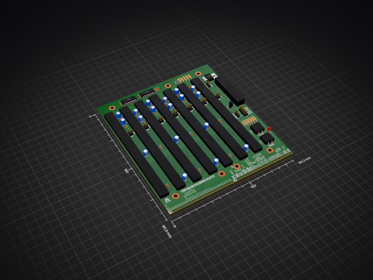
1 - ATX 16 bit ISA passive backplane is an open-source printed circuit board by FredericSegard, from the FredericSegard/Fr80 repository on GitHub. It is a 2-layer board of 161.3 × 181.6 mm with 94 parts on 134 nets, routed with 4,221 tracks and 128 vias.
It is built around the 74HCT14D, 74HCT74D and LM7905T, with the DS1813-5+ among its other parts. Its parts include 41 capacitors, 24 connectors, 11 resistors, 3 ICs and 2 diodes.


This repo will contain all the elements for a complete Z80 system (Work in progress)
The goal is to first make a ubiquitous backplane that could accommodate many 8 or 16-bit architectures, including most x86 that is compatible, Z80, eZ80, z8000, 65C02, 65C816, 6809... You name it, it should handle it. The only difference is in the PCB labeling. I have labeled the breadboard header as per the PC ISA standard on row 1, row 2 is for the Z80, and row 3 is for the 65C02. The breadboard pins are pin-to-pin mapped A1-A13 on the left, and B1-B31 on the right.
This backplane follows the ISA power rail standard. This means the +5, ground, +12V, and -12V lanes are where they should be. However, there is provision for a -5V regulator, since most ATX PSUs no longer support it. And since 3.3V is more prevalent these days, I have assigned the -5V lane to +3.3V. However, you can select which voltage you need by simply changing a jumper's position. There is an alternate barrel jack power input for 5 volts only. There is a provision for a 3.3V regulator should you need it. Both power sources are soft power-on. Jumpers are present to repurpose the button, since electrically, they could not be tied together.
It is a passive backplane, so there should be no interference with other signal types. So in theory, you could reassign all non-power rail buses, except for the reset lane and A7 and A8. The reset circuit, which is jumper selectable between active high or active low, cannot be reassigned. And the CPU activity LED, which monitors A7 or A8 (jumper selectable), can't also be moved.
I have just received the PCBs from the fab house. I will assemble it and let you know if everything works as intended.

I made several iterations of the CPU board, but now I'm satisfied with this revision 3. It's a very compact 100mm² 4-layer board, that contains the CPU, 128KB Flash, 512KM RAM, bank switching circuitry, a priority interrupt encoder, a CTC, and an SIO with USB ports (type A and type B).
I gave myself a challenge to fit as much as possible in a 100mm² PCB, all the while managing to put in a ZIF socket and some blinkenlights. The board is so stuffed with components, that I needed to place the bypass capacitors in the sockets, as well as some resistors.
I will send out the Gerber for manufacturing, and keep you posted.

| Qty | Value | Footprint | References |
|---|---|---|---|
| 23 | 1µF | Capacitor_THT:C_Disc_D3.0mm_W1.6mm_P2.50mm | C12, C16, C17, C18, C20, C21, C22, C23, C25, C26, C27, C28, C30, C32, C34, C36 +7 |
| 18 | 10µF | Capacitor_THT:CP_Radial_D6.3mm_P2.50mm | C1, C2, C3, C4, C6, C10, C11, C13, C14, C15, C19, C24, C29, C31, C33, C35 +2 |
| 7 | MH | 0_Library:MountingHole_M3.96_Pad_Via_ATX | H1, H2, H3, H4, H5, H6, H7 |
| 4 | 220 | Resistor_THT:R_Axial_DIN0207_L6.3mm_D2.5mm_P10.16mm_Horizontal | R1, R2, R11, R17 |
| 2 | 10K | Resistor_THT:R_Axial_DIN0207_L6.3mm_D2.5mm_P10.16mm_Horizontal | R4, R14 |
| 2 | Logo_Open_Hardware_Small | Symbol:OSHW-Logo2_7.3x6mm_SilkScreen | LOGO1, LOGO2 |
| 1 | 1K | Resistor_THT:R_Axial_DIN0207_L6.3mm_D2.5mm_P10.16mm_Horizontal | R8 |
| 1 | 1N4148 | Diode_THT:D_DO-35_SOD27_P7.62mm_Horizontal | D2 |
| 1 | 20K | Resistor_THT:R_Axial_DIN0207_L6.3mm_D2.5mm_P10.16mm_Horizontal | R9 |
| 1 | 2K2 | Resistor_THT:R_Axial_DIN0207_L6.3mm_D2.5mm_P10.16mm_Horizontal | R16 |
| 1 | 2K7 | Resistor_THT:R_Axial_DIN0207_L6.3mm_D2.5mm_P10.16mm_Horizontal | R15 |
| 1 | 330 | Resistor_THT:R_Axial_DIN0207_L6.3mm_D2.5mm_P10.16mm_Horizontal | R10 |
| 1 | 3V/-5V | Connector_PinHeader_2.54mm:PinHeader_1x03_P2.54mm_Vertical | J19 |
| 1 | 74HCT14 | Package_DIP:DIP-14_W7.62mm | U1 |
| 1 | 74HCT74 | Package_DIP:DIP-14_W7.62mm | U3 |
| 1 | A: Component Side | Connector_PinHeader_2.54mm:PinHeader_1x31_P2.54mm_Vertical | J2 |
| 1 | ACT LED | 0_Library:PinHeader_1x2_Vertical (Modified) | J20 |
| 1 | ACTIVITY | LED_THT:LED_D3.0mm | D3 |
| 1 | ATX POWER | 0_Library:ATX_PSU_CONN | J10 |
| 1 | B: Back Side | Connector_PinHeader_2.54mm:PinHeader_1x31_P2.54mm_Vertical | J3 |
| 1 | BUS 1 | 0_Library:ISA_Connector_98 | J1 |
| 1 | BUS 2 | 0_Library:ISA_Connector_98 | J4 |
| 1 | BUS 3 | 0_Library:ISA_Connector_98 | J5 |
| 1 | BUS 4 | 0_Library:ISA_Connector_98 | J6 |
| 1 | BUS 5 | 0_Library:ISA_Connector_98 | J7 |
| 1 | BUS 6 | 0_Library:ISA_Connector_98 | J8 |
| 1 | BUS 7 | 0_Library:ISA_Connector_98 | J9 |
| 1 | DS1813 | Package_TO_SOT_THT:TO-92L_Inline_Wide | RS1 |
| 1 | Housing | 0_Library:ATX_Backplane | N1 |
| 1 | IE12 | 0_Library:PinHeader_2x2_Vertical (Modified) | J22 |
| 1 | IE23 | 0_Library:PinHeader_2x2_Vertical (Modified) | J23 |
| 1 | IE34 | 0_Library:PinHeader_2x2_Vertical (Modified) | J24 |
| 1 | IE45 | 0_Library:PinHeader_2x2_Vertical (Modified) | J25 |
| 1 | IE56 | 0_Library:PinHeader_2x2_Vertical (Modified) | J26 |
| 1 | IE67 | 0_Library:PinHeader_2x2_Vertical (Modified) | J27 |
| 1 | IE78 | 0_Library:PinHeader_2x2_Vertical (Modified) | J28 |
| 1 | LM7905 | Package_TO_SOT_THT:TO-220-3_Horizontal_TabDown | U4 |
| 1 | POWER | 0_Library:Pushbutton_12mm_LED | SW1 |
| 1 | PWR_LED | 0_Library:PinHeader_1x2_Vertical (Modified) | J13 |
| 1 | PWR_SW | 0_Library:PinHeader_1x2_Vertical (Modified) | J14 |
| 1 | RESET | 0_Library:Pushbutton_12mm_LED | SW2 |
| 1 | RST POLARITY | Connector_PinHeader_2.54mm:PinHeader_1x03_P2.54mm_Vertical | J16 |
| 1 | RST_LED | 0_Library:PinHeader_1x2_Vertical (Modified) | J17 |
| 1 | RST_SW | 0_Library:PinHeader_1x2_Vertical (Modified) | J18 |
FredericSegard/Fr80
Z80 Homebrew computer, code-named Fre80, pronounced Freddy.

FredericSegard/Fr80
Z80 Homebrew computer, code-named Fre80, pronounced Freddy.

Toysoft/mb386sx-rc2016
The origin of this project is the M396F motherboard replica by Marco Both. Marco replicated the PCB layout of a certain revision of M396F motherboard. He didn't provide the schematic.


thorpej/pg68k
The 68k Playground, a 680x0-based home-brew computer with multiple CPU options


schlae/snark-barker-mca
A Sound Blaster compatible sound card for Micro Channel bus computers


It measures 161.3 × 181.6 mm and has 2 copper layers, 1.6 mm thick.
94 parts, built around the 74HCT14D, 74HCT74D, LM7905T and DS1813-5+. The full list of its parts is on this page, with links to each part's symbol and footprint where PCBKit's library has them.
From the FredericSegard/Fr80 repository on GitHub, at the commit this page was made from: the board is 1 - ATX 16 bit ISA passive backplane/1 - ATX 16 bit ISA passive backplane.kicad_pcb and its schematic 1 - ATX 16 bit ISA passive backplane/1 - ATX 16 bit ISA passive backplane.kicad_sch. PCBKit opens the board in the browser, with nothing to install.
Its repository states no licence, so its author keeps all rights: ask FredericSegard before reusing the design.