This usermod enables connection of an ESP32C3 (you can build the firmware for other boards) to a flight controller , allowing users to select specific presets with a switch on their remote.
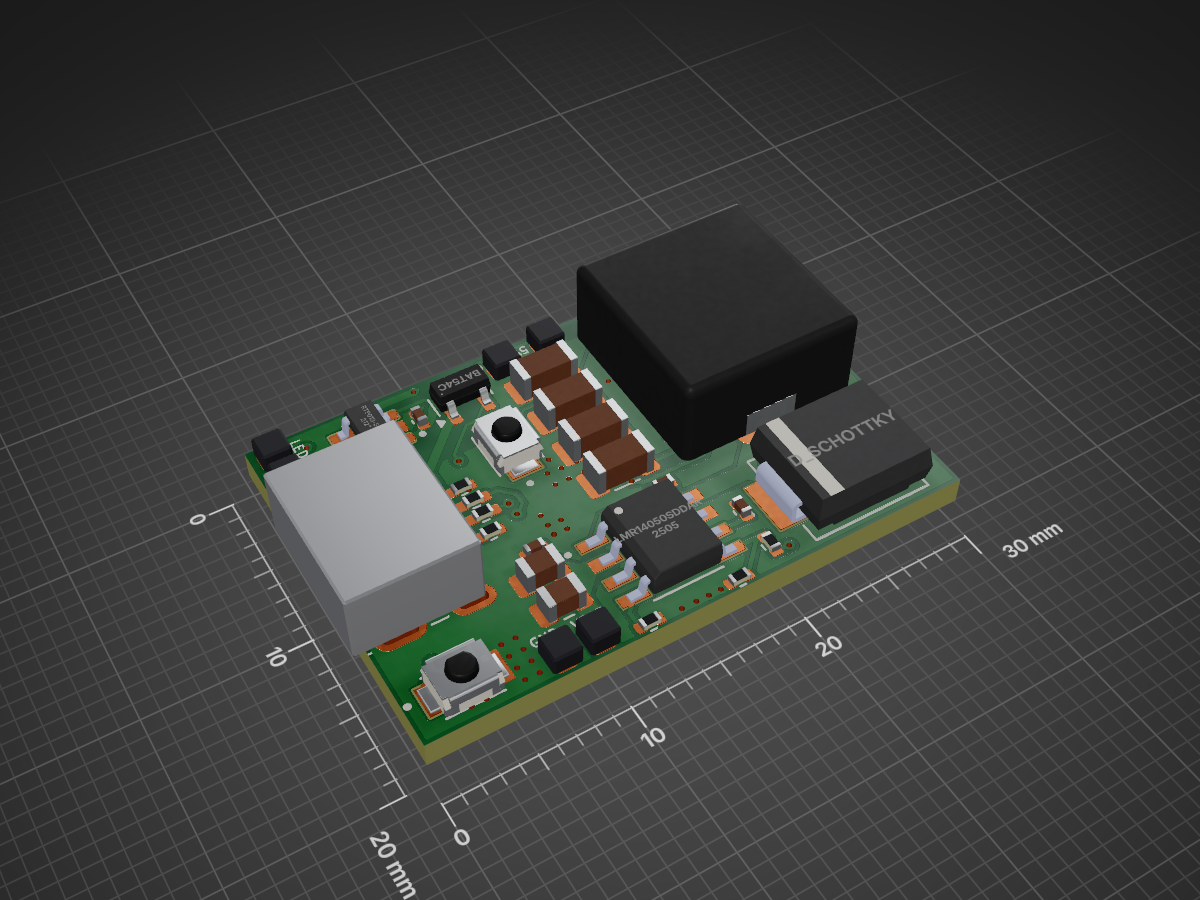
PCB WLED Spec 7 is an open-source printed circuit board by Torie3, from the Torie3/WLED-Usermod-SPEC7led repository on GitHub, published under the MIT licence. It is a 2-layer board of 30 × 20 mm with 55 parts on 47 nets, routed with 327 tracks and 222 vias.
It is built around the ESP32-C3, LMR14050SDDAR and RT9013-33GB, with the B3U-1000P, 2450AT18A100E and BAT54C among its other parts. Its parts include 22 capacitors, 13 resistors, 8 switches, 3 ICs and 2 diodes. It belongs with the ESP32 and RISC-V boards of this library.
This usermod enables connection of an ESP32C3 (you can build the firmware for other boards) to a flight controller , allowing users to select specific presets with a switch on their remote. Originally developed for Spec7 quads, this mod can be applied to any project where a preset needs to be activated based on a PWM signal received on a designated pin.
⚙️ How It Works
WLED is a project that allows easy control of addressable RGB lights. Our focus is on enabling users to switch between different presets set up in the WLED app using a physical switch on the controller. This is achieved by leveraging a built-in feature in Betaflight or Inav that generates a PWM (Pulse Width Modulation) signal on a specific pin—typically used for controlling servos. While we could have read data directly from the receiver, we opted for the PWM approach for several reasons outlined below.
Advantages and Disadvantages of Using PWM
Advantages:
Compatible with Any Remote Protocol Supported by Betaflight: Allows flexibility across various remote protocols.
Minimal Data Processing from Receiver: Only the PWM signal is processed, improving the program’s speed and efficiency.
Standalone Use with PWM Receivers: Can operate as a standalone unit with just the controller and LEDs, without a flight controller (FC).
Protocol Agnostic: No need to adapt to specific protocols, making the setup easily adaptable.
Avoids UART Conflicts: WLED may interfere with LED-receiver communication, particularly when multiple UARTs are used (one for the receiver and one for LEDs), as adding a software serial port can consume significant processing power.
Disadvantages:
Requires a Flight Controller or PWM Receiver: Cannot function as a standalone unit with just the receiver, ESP, and LEDs.
Single-Channel Limitation: Multiple channels for selecting presets would require additional wiring and pins on the FC.
Consumes a Pin on the Flight Controller: Typically, the LED pin is used, but additional motor pins may also be viable.
Advantages and Disadvantages of Direct Receiver Connection
Advantages:
Access to Full Receiver Data: Allows use of multiple channels.
Standalone Operation: Can function with just the receiver, ESP, and LEDs.
No Flight Controller Pin Usage: Frees up all pins on the flight controller.
Disadvantages:
Requires Soldering on Receiver Pads: Soldering two wires onto a single receiver pad can be cumbersome.
Limited to One Remote Protocol: Only one remote protocol can be used in this configuration.
Considering these factors, we chose the PWM option, which offers a balanced approach in terms of flexibility, performance, and ease of setup. For instructions on setting up the system, refer to the Quick Start Guide.
💡 Quick Start Guide
Betaflight Setup
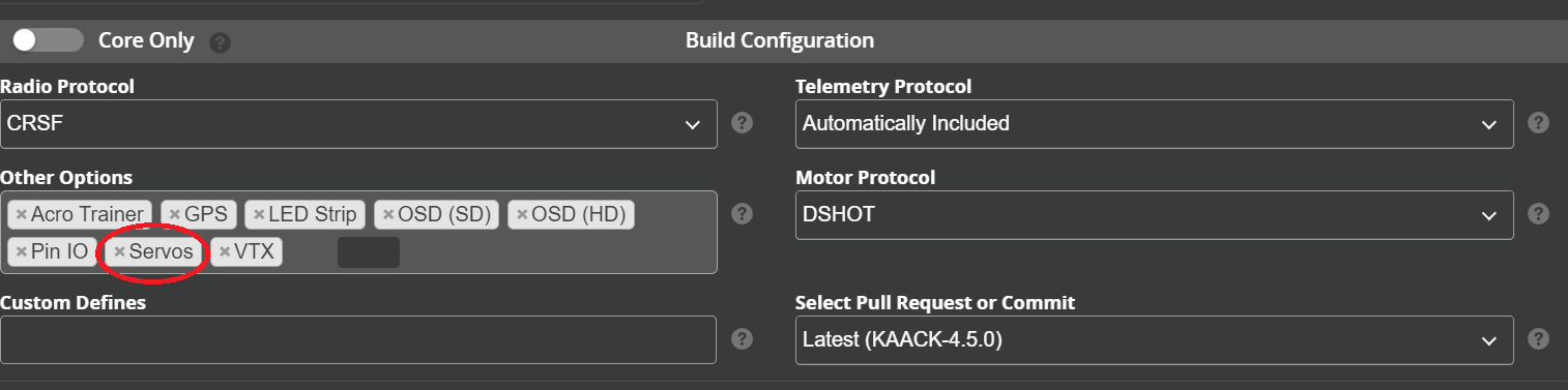
Enable Servo on Flight Controller
Ensure you flash your flight controller with servo enabled.
Standard Flight Controller Setup
Set up your flight controller as you normally would.
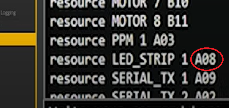
Check Resource Pins in CLI
Open the CLI and paste the following command to display all resources and their pin assignments:
resource
Find resource LED_STRIP 1 in the output and note the pin number next to it (e.g., A08).
Reassign LED Strip Pin to Servo
Enter the following commands in the CLI to remove the LED strip assignment from this pin and assign it to Servo 1:
text
resource LED_STRIP none
resource SERVO 1 "your noted pin number from step 4"
save
Configure Servo Settings
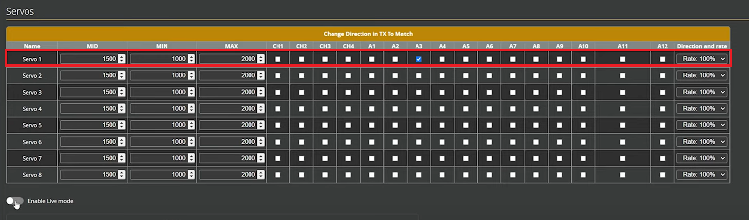
Go to the Servo tab and adjust the settings marked in the red box in the image below. Only the channel associated with the button to switch presets needs to be adjusted here. In the Receiver tab, you can check which button corresponds to which action. (We recommend using a 6-button switch on your controller; however, other setups may work, although results may vary.)
Note: This configuration won’t work when connected to your computer unless “live mode” is enabled.
Hardware Setup
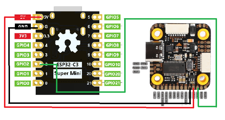
Connect Ground
Connect the ground on your flight controller to the ground on the ESP. This is mandatory, as it sets a shared reference.
Connect Data Pin
Connect the LED pin on your flight controller to gpio 2 on the ESP (make sure it's not pin 2, because on some boards they aren't the same). This wire carries the data.
Power the ESP and LEDs
Power the ESP as needed, and connect the LEDs like a standard WLED setup.
Note: The following diagram provides an example for wiring. Do not copy it exactly; please research how to power your ESP safely. We are not liable for any physical or material damage.
Custom PCB
Warning: this pcb has not yet been tested, you can find all of the design files under the folder pcb. You should check the pcb design befor ordering.
If you want to order and test this pcb, we have added an excel file that includes all of the components. The components can be ordered from mouser and JLCPCB. Feel free to use other components.
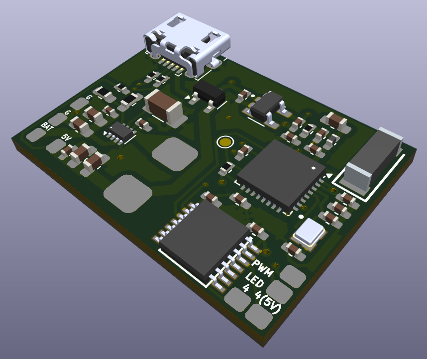
We recently introduced a custom PCB that integrates all the necessary components to run WLED on drones. This board includes a 5V@3A buck converter, capable of stepping down 3s-6s voltage to a stable 5V supply.
The PCB measures 29mm × 21mm, making it a perfect fit for a Spec7 quadcopter. Since only one side of the board is populated, you don’t need to worry about clearance on the mounting surface.
However, we highly recommend placing a layer of electrical tape beneath the PCB to prevent potential short circuits, as carbon fiber is conductive.
At its core, the board features an ESP32-C3, complete with all essential supporting components for power management and Wi-Fi transmission.
To simplify wiring, we've integrated a logic level converter, which shifts the ESP32-C3's 3.3V signal to 5V, ensuring proper operation of LED strips.
Additionally, we've included an extra GPIO pin, which can be used for:
Receiving an input from the flight controller
Connecting an additional LED strip
This extra GPIO is available as both a 3.3V pad and a 5V pad (via the logic level converter), allowing seamless integration with LED strips.
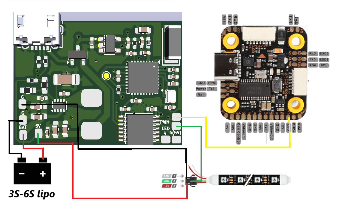
Below is the wiring diagram. Please note that your flight controller may vary, so be sure to check its specifications before wiring.
Note: you should have a common ground between the PCB and flight controller to ensure proper operation of the PCB.
ESP Setup
This guide covers setup on Windows only. (Linux users should be able to manage on their own. Mac users: consider upgrading your hardware! Just kidding 😊)
Download Firmware
Navigate to build_output/releases, select the appropriate folder for your board, and download the .bin firmware file.
For ESP32 devices, download the bootloader file located in .pio/build/your_board_here.
Set Up Programming Tool
Follow the steps in this guide to install Python. You may skip steps 4 and 7 as they are optional.
Once Python is installed, open Command Prompt (cmd) and run pip install esptool to install esptool.
Connect ESP to Computer
While holding the boot button on the ESP, plug it into your PC.
Open Device Manager and note the COM port your ESP is connected to.
Upload Firmware
Note: These commands should be executed in the Command Prompt (cmd) on your Windows PC. You do not need to run it as an administrator.
If you're unsure how to open Command Prompt, click the Windows Start button, type cmd, and select the Command Prompt application. This will open a terminal where you can enter commands.
After completion, disconnect the ESP from your PC.
Final Steps
Set up WLED as usual, ensuring you create six presets to avoid errors when switching. This setup is compatible with six-button switches (e.g., Radiomaster Boxer and TX16s). Future updates will include support for two- and three-position switches.
Enjoy your new LED setup on your Spec 7 quad!
Disclaimer:
If you are prone to photosensitive epilepsy, we recommended you do not use this software.
If you still want to try, don't use strobe, lighting or noise modes or high effect speed settings.
As per the MIT license, I assume no liability for any damage to you or any other person or equipment.
This usermod enables connection of an ESP32C3 (you can build the firmware for other boards) to a flight controller , allowing users to select specific presets with a switch on their remote.
microSD to SD adapter card with ESP32 onboard. Allows wireless access to the microSD card without removing it from its slot. Useful for car infotainment systems.
Three autonomous drones that search a flood zone, find survivors, geotag them, and drop medical kits — with no network, no pilot, and one operator who only presses start.
i made this project as a speedrun before the end of fallout for funsies. it is (hopefully) tetris on a keychain! how it will work is that you will be able to play tetris on the oled screen by moving the pcb around, and…
40 parts
Questions
How big is the PCB WLED Spec 7 PCB?
It measures 30 × 20 mm and has 2 copper layers, 1.6 mm thick.
What parts does the PCB WLED Spec 7 use?
55 parts, built around the ESP32-C3, LMR14050SDDAR, RT9013-33GB and B3U-1000P. The full list of its parts is on this page, with links to each part's symbol and footprint where PCBKit's library has them.
Where can I download the PCB WLED Spec 7 KiCad files?
From the Torie3/WLED-Usermod-SPEC7led repository on GitHub, at the commit this page was made from: the board is pcb/REV2/PCB WLED Spec 7/PCB WLED Spec 7.kicad_pcb and its schematic pcb/REV1/kicad data/wled usermod.kicad_sch. PCBKit opens the board in the browser, with nothing to install.
Can I use the PCB WLED Spec 7 design in my own project?
Its repository publishes it under the MIT licence: you may reuse it on that licence's terms (keep the author's notice, and for a copyleft licence share your changes alike).