4 layers85 × 57.5 mm
 TimGremalm/LightBoxNano6
a generic PCB for controlling LED's both LED strip and WS2812
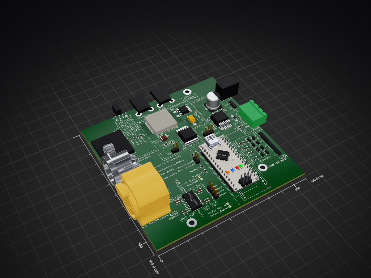
LightBoxNano is an open-source printed circuit board by TimGremalm, from the TimGremalm/LightBoxNano repository on GitHub, published under the GPL-3.0 licence. It is a 2-layer board of 109.8 × 109.9 mm with 76 parts on 74 nets, routed with 696 tracks and 35 vias.
It is built around the IRLML6344, BTS50055-1TMC and ESP32-PICO-KIT, with the PESD5V0X1UAB among its other parts. Its parts include 2 connectors, 1 switch and 1 fuse. It belongs with the lEDs and displays boards and the ESP32, AVR (ATmega, ATtiny) and RISC-V boards of this library.


a generic LED controller that can be populated for either RGBW LED strip or addressable LED strip like WS2812.
It has the option for populating a pair of potentiometer, and a 5 way slider switch for controlling light modes.
An Arduino Nano is mounted using ordinary 2.54mm pitch pin headers. Optionally a ESP32 Pico Kit can be mounted instead of the Nano, this is much more expensive it is a more powerful MCU and have WiFi.
A RS485 receiver and a pair of XLR connectors can also transform the LED controller into a DMX driver.
The input voltage to LightBoxNano are called VIN and can range from 5 to 30V. Make sure to only feed LightBoxNano with a voltage that the LED strip can handle. The maximum voltage is limited by the maximum voltage of the IRLML6344 Mosfets and of what the LED strip can handle.
If using 5V on Vin you need to read "Logic rail" to populate it correctly.
The positive rail for the LED strip driver is directly fed from VIN, it's usually 12V.
The positive rail for the addressable LED strip driver is directly fed from VIN, it's usually 5V.
The logic rail should be 5V and feed the micro controller.
There is 2 options for the logic rail:
Note that the logic rail bypasses Vin_fused.
The buck converter using TI's guide: https://webench.ti.com/power-designer/switching-regulator/select
https://webench.ti.com/appinfo/webench/scripts/SDP.cgi?ID=572687AF787DDED1
There is 2 options for input protection:
A much cheaper option then the high side switch, but one time use only. Populate with a appropriate 1206 fast blow fuse. Example: Fuse Fast Blow 10A 1206 MCCFB1206TFF/10
No reverse polarity protection exist when using a classic fuse.
The Infineon BTS50055-1TMC is a highside high current power switch with buildt in reverse polarity and temperature protection.
It's also used to measure current consumption; Current_Feedback as analog output. To enable the high power switch Enable_Vin_fused must be driven low.
Both Current_Feedback and Enable_Vin_fused goes to the MCU so it can act on over current and act as a resettable fuse.
Vin_fused
| Channel | Arduino Nano | ESP32 |
|---|---|---|
| Current_Feedback | A0 (PC0) | IO38 |
| Enable_Vin_fused | D13 (PB5) | IO37 |
This is made for LED strip that have red, green, blue and white channels that have a common positive rail like +12V. The LED driver can drive 4 output channels in constant voltage mode at 5A each. The channel can drive up to 10A current if an optional IRLML6344 is mounted. One color channel on a 5m LED strip consisting of 300 LED's will draw 6A (20mA x 300px) when fully lit. A full RGB strip 18A, and a RGBW strip 24A.
| Channel | Arduino Nano | ESP32 |
|---|---|---|
| Red | D5 (PD5) | IO26 |
| Green | D6 (PD6) | IO27 |
| Blue | D9 (PB1) | IO13 |
| White | D10 (PB2) | IO15 |
Addressable LED strip is hooked up directly to VIN and the data pin is going to micro controller via a 1k resistor.
| Channel | Arduino Nano | ESP32 |
|---|---|---|
| Addressable | D3 (PD3) | IO25 |
Two potentiometers can optionally be mounted. They are pulled up to 3.3V, so you won't get the full range on the Nano.
| Channel | Arduino Nano | ESP32 |
|---|---|---|
| POT_1 | A1 (PC1) | IO26 |
| POT_2 | A2 (PC2) | IO27 |
A 10 position rotary coded switch can optionally be mounted for selecting different modes.
| Channel | Arduino Nano | ESP32 |
|---|---|---|
| SwCode1 | D7 (PD7) | IO14 |
| SwCode2 | D8 (PB0) | IO12 |
| SwCode4 | D11 (PB3) | IO2 |
| SwCode8 | D12 (PB4) | IO4 |
10 position switch is coded in binary.
| Code | 0 | 1 | 2 | 3 | 4 | 5 | 6 | 7 | 8 | 9 |
|---|---|---|---|---|---|---|---|---|---|---|
| 1 | * | * | * | * | * | |||||
| 2 | * | * | * | * | ||||||
| 4 | * | * | * | * | ||||||
| 8 | * | * |
Also a pin header of the Arduino Nano will be easily assessable for hooking up random stuff.
A RS-485 transceiver can optionally be mounted for sending and receiveing DMX512. It uses ADM2687E which isolates the RS-485 bus from the low voltage micro controller side. This is important as electrical errors down the bus can propagage along the bus. ADM2687E also isolates the power on the bus side by a buildt in DC to DC converter.
The tranceiver can be set to send DMX data if the jumper links "Link_DriverOutputA1" and "Link_DriverOutputB1" is soldered.
| Jumper | Description |
|---|---|
| Link_DriverOutputA1 | Links the Z (Driver Inverting Output) to DMX+ |
| Link_DriverOutputB1 | Links the Y (Driver Noninverting Output) to DMX- |
| Receiver_Disable1 | Pulls RE (Receiver Enable) to High which disables receiver |
| Receiver_Enable1 | Pulls RE (Receiver Enable) to Low which enables receiver |
| Driver_Enable1 | Pulls DE (Driver Enable) to High which enables sender |
| Driver_Disable1 | Pulls DE (Driver Enable) to Low which disables sender |
| Link_TransceiverGnd_To_DMXgnd1 | Links DMX bus Gnd to ADM2687E Gnd2 |
| Link_DMXgnd_To_DMXchassignd1 | Links DMX ground shield to ADM2687E Gnd2 |
DMX Send and Receive can be hooked up to UART channels on a MCU. Receiver Enable and Driver Enable can also be driven by the micro controller (only ESP32).
| Channel | Arduino Nano | ESP32 |
|---|---|---|
| DMX_Send | D1 TX (PD0) | IO21 |
| DMX_Receive | D0 RX (PD1) | IO22 |
| DMX_ReceiveEnable | N.C | IO19 |
| DMX_DriveEnable | N.C | IO23 |
An Arduino Nano V3 (ATmega328) is selected because it's cheap, available and have enough power for most applications.
Another option is to mount a ESP32 Pico Kit instead which is much more powerful and have built in WiFi.
| Qty | Value | Footprint | References |
|---|---|---|---|
| 8 | 10k | Resistors_SMD:R_0603_HandSoldering | R_sw1, R_sw2, R_sw4, R_sw8, Rblue_pulldown1, Rgreen_pulldown1, Rred_pulldown1, Rwhite_pulldown1 |
| 8 | 1k | Resistors_SMD:R_0603_HandSoldering | Radd1, Rblue1, Renable1, Rfeedback1, Rfeedback2, Rgreen1, Rred1, Rwhite1 |
| 8 | IRLML6344 | TO_SOT_Packages_SMD:SOT-23 | Qb1, Qb2, Qg1, Qg2, Qr1, Qr2, Qw1, Qw2 |
| 4 | 100nF | Capacitors_SMD:C_0603_HandSoldering | Cdmx1, Cdmx4, Cdmx6, Cdmx7 |
| 4 | MountingHole | Mounting_Holes:MountingHole_3.2mm_M3_Pad | H1, H2, H3, H4 |
| 2 | 10k | Potentiometers:Potentiometer_Alps_RK09K_Vertical | RV_pot1, RV_pot2 |
| 2 | 10nF | Capacitors_SMD:C_0603_HandSoldering | Cdmx2, Cdmx5 |
| 2 | 10µF | Capacitors_SMD:C_0603_HandSoldering | Cdmx3, Cdmx8 |
| 2 | Conn_02 DNP | Pin_Headers:Pin_Header_Straight_1x02_Pitch2.54mm | J5V1, Jpowerswitchbreakout1 |
| 2 | DriverEnable | ConnTest:JUMPER-SOLDER-SMD | Driver_Disable1, Driver_Enable1 |
| 2 | LinkDriverOutput | ConnTest:JUMPER-SOLDER-SMD | Link_DriverOutputA1, Link_DriverOutputB1 |
| 1 | 100µF 50V 27mΩ | Capacitors_SMD:CP_Elec_10x10.5 | Cvin1 |
| 1 | 120R DNP | Resistors_SMD:R_0603_HandSoldering | R_termination1 |
| 1 | 18µF 50V 35mΩ | Capacitors_SMD:CP_Elec_8x10 | Cbi1 |
| 1 | 300R | Resistors_SMD:R_0603_HandSoldering | Rled1 |
| 1 | 4.7µF 10V 1.4Ω | Capacitors_SMD:C_1206_HandSoldering | Cbo1 |
| 1 | Analog-Devices-ADM2687E_RS485 | Housings_SOIC:SOIC-16W_7.5x12.8mm_Pitch1.27mm | U_DMX1 |
| 1 | Arduino-Nano-V3 | ArduinoNano:Arduino-Nano-V3_Jumper | MCU_nano1 |
| 1 | BTS50055-1TMC | TO_SOT_Packages_SMD:TO-263-7_TabPin4 | Qhigh1 |
| 1 | Barrel Jack Switch 5A 2mm | LightBoxNanoFootprints:BarrelJack_SPC21364 | Jb1 |
| 1 | Conn_03 | LightBoxNanoFootprints:PrototypeArea | PrototypeArea1 |
| 1 | Conn_03 DNP | Pin_Headers:Pin_Header_Straight_1x03_Pitch2.54mm | Jvoltagebreakout1 |
| 1 | Conn_04 | Pin_Headers:Pin_Header_Straight_1x04_Pitch2.54mm | J_DMX_Breakout1 |
| 1 | ESP32-PICO-KIT | ESP32:ESP32-PICO-KIT_Jumper | MCU_esp1 |
| 1 | Fuse DNP | Fuse_Holders_and_Fuses:Fuse_SMD1206_HandSoldering | F1 |
| 1 | Inductor 47µH 42.7mΩ | LightBoxNanoFootprints:Inductor_IHLP6767GZER470M11 | Lbuck1 |
| 1 | Knitter-Switch DRR4010 | Knitter-Switch:DRR4010 | SW1 |
| 1 | LED Red | LEDs:LED_0603_HandSoldering | LEDpwr1 |
| 1 | LM2596SX 5V 3A | TO_SOT_Packages_SMD:TO-263-5_TabPin3 | Ubuck1 |
| 1 | LOGO | LightBoxNanoGraphics:LedAlertLogotype | G*** |
| 1 | Link Vin to 5V | ConnTest:JUMPER-SOLDER-SMD | Link_Vin_To_5V1 |
| 1 | LinkDmxGndToChassiGnd | ConnTest:JUMPER-SOLDER-SMD | Link_DMXgnd_To_DMXchassignd1 |
| 1 | LinkTransceiverGndToDmxGnd | ConnTest:JUMPER-SOLDER-SMD | Link_TransceiverGnd_To_DMXgnd1 |
| 1 | MSTBA2 | PhoenixContact:PhoenixContact-MSTBA_2,5_4-G-5,08_2pole | Jc1 |
| 1 | MSTBA3 | PhoenixContact:PhoenixContact-MSTBA_2,5_4-G-5,08_3pole | Jadd1 |
| 1 | MSTBA5 | PhoenixContact:PhoenixContact-MSTBA_2,5_4-G-5,08_5pole | Jrgbw1 |
| 1 | PESD5V0X1UAB | Diodes_SMD:D_SOD-523 | ESD1 |
| 1 | ReceiverEnable | ConnTest:JUMPER-SOLDER-SMD | Receiver_Enable1 |
| 1 | ReveiverEnable | ConnTest:JUMPER-SOLDER-SMD | Receiver_Disable1 |
| 1 | Schottky 200V 10A | TO_SOT_Packages_SMD:TO-252-2_Rectifier | Db1 |
| 1 | XLR_3pin_Female_Ground | XLR_Neutrik:XLR_3pole-female_Horizontal_PCB_mount_NC3FAAH2 | XLR_Female1 |
| 1 | XLR_3pin_Male_Ground | XLR_Neutrik:XLR_3pole-male_Horizontal_PCB_mount_NC3MAAH | XLR_Male1 |
The 75 most common of 76 parts.

willem-pennings/Air-Quality-Sensor
Design files for a Home Assistant-compatible air quality sensor/monitor

jc-SpaceXp/Spekky-Matrix
Spectrum analyser displayed on a LED matrix board connected to a STM32 device


I-M-Robotics-Lab/STM32-Quadcopter
Quadcopter design based on STM32F411CEU Blackpill flight controller. Compatible with INAV 6.0 firmware.

kerikun11/IR-Station
Infrared Remote Controller with ESP8266 WiFi-module. You can control your home appliances with your smartphone or laptop.

freakontrol/stmbl
THE AUTHORS OF THIS SOFTWARE ACCEPT ABSOLUTELY NO LIABILITY FOR ANY HARM OR LOSS RESULTING FROM ITS USE. IT IS EXTREMELY UNWISE TO RELY ON SOFTWARE ALONE FOR SAFETY.

leafai-io/leaf-node-v3.x
Modular node for sensor monitoring and device control in grow environments.
It measures 109.8 × 109.9 mm and has 2 copper layers, 1.6 mm thick.
76 parts, built around the IRLML6344, BTS50055-1TMC, ESP32-PICO-KIT and PESD5V0X1UAB. The full list of its parts is on this page, with links to each part's symbol and footprint where PCBKit's library has them.
From the TimGremalm/LightBoxNano repository on GitHub, at the commit this page was made from: the board is LightBoxNano.kicad_pcb. PCBKit opens the board in the browser, with nothing to install.
Its repository publishes it under the GPL-3.0 licence: you may reuse it on that licence's terms (keep the author's notice, and for a copyleft licence share your changes alike).