4 layers100 × 135 mm
Microver2026 Modular Final
Tim4769/Microver
Swiss Rover Challenge rover project with final electronics, mechanical handoff files, PCB validation firmware, and shared project assets.
66 parts
 Tim4769/Microver
Swiss Rover Challenge rover project with final electronics, mechanical handoff files, PCB validation firmware, and shared project assets.
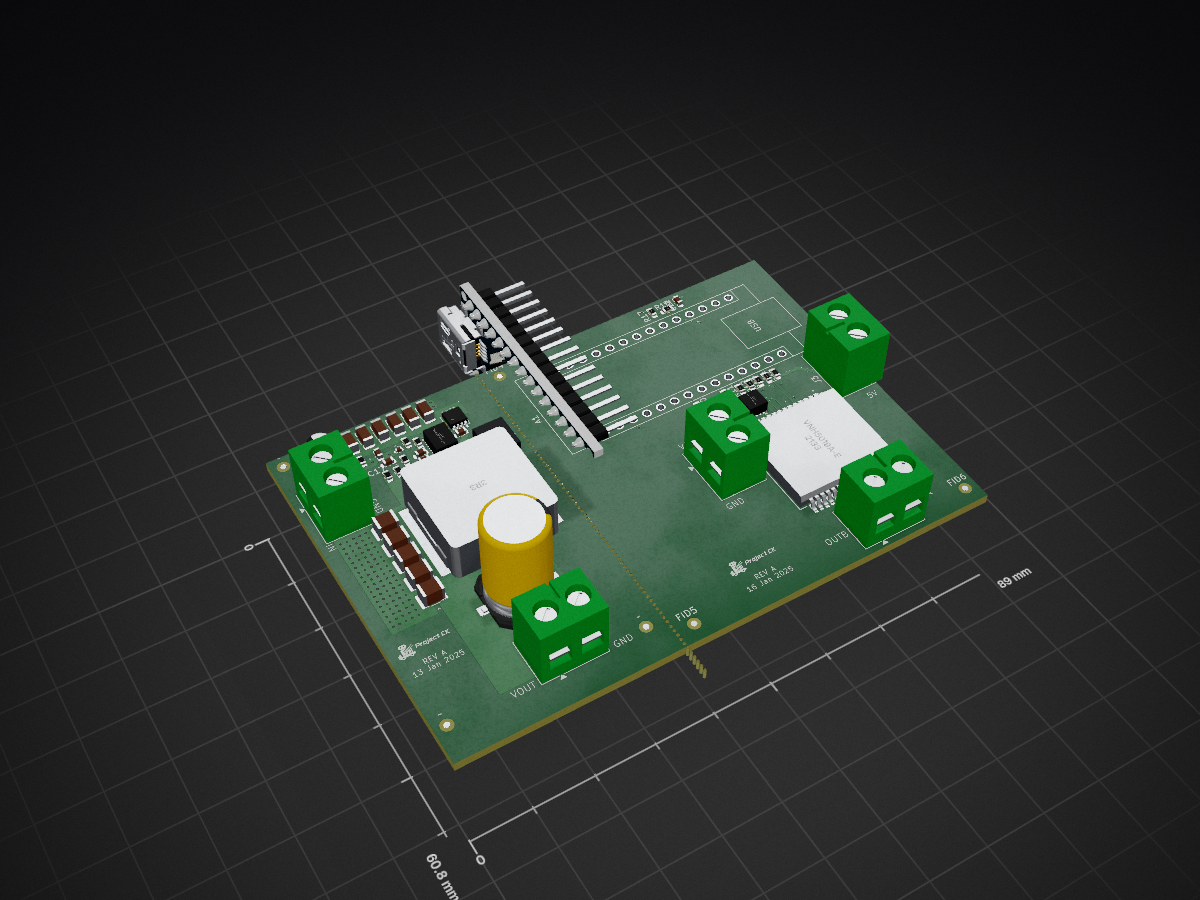
Buck is an open-source printed circuit board by Tim4769, from the Tim4769/Microver repository on GitHub. It is a 4-layer board of 89 × 60.8 mm with 68 parts on 65 nets, routed with 261 tracks and 177 vias.
It is built around the LM5146QRGYTQ1, CSD18543Q3A and BSC014N06NS. Its parts include 22 capacitors, 18 resistors, 5 connectors, 3 ICs and 2 transistors. It belongs with the power and robots and motor control boards and the AVR (ATmega, ATtiny) boards of this library.


Microver is a compact rover built for the Swiss Rover Challenge. This repository collects the project's electronics, mechanical CAD, software scaffold, PCB test firmware, photos, and shared assets in one place.
| Area | Path | Contents |
|---|---|---|
| Electronics | hardware/final/README.md | Active PCB revisions, KiCad projects, manufacturing outputs, and validation notes. |
| Mechanical | mechanical/README.md | Rover assemblies, wheel pods, chassis parts, mechanisms, mounts, and STEP exports. |
| Software | software/ | Python rover-control scaffold with camera and control services. |
| PCB test firmware | hardware/pcb_testing_firmware/README.md | Arduino sketches and docs for board bring-up and electronics validation. |
| Power diagrams | hardware/flow_charts/README.md | Power-system flow charts and supporting diagrams. |
Electronics
hardware/final/; archived board spins live under hardware/archive/.Mechanical
mechanical/assemblies/ and mechanical/components/.Software
software/ is the autonomy-ready rover software workspace for control, camera, perception, navigation, and system integration.hardware/pcb_testing_firmware/ contains electronics bring-up and validation sketches only; it is separate from the final software stack.hardware/ - PCB designs, manufacturing files, archived board revisions, power diagrams, and PCB validation firmware.mechanical/ - CAD assemblies, exported STEP components, manufacturing notes, and mechanical integration references.software/ - Raspberry Pi control software scaffold and future rover software workspace.photos/ - Build, test, and competition photos.logo/ - Current and legacy logo assets.jingle/ - Project audio assets.Microver_presentation_final.pdf - Final presentation and system overview.All rights reserved. No permission is granted to use, copy, modify, or distribute this repository or its contents without prior written consent. See LICENSE for exact terms.
Contact: Tim Wang - timwang007@outlook.com.
| Qty | Value | Footprint | References |
|---|---|---|---|
| 6 | 4.7 uF | Capacitor_SMD:C_1206_3216Metric | C2, C3, C4, C6, C7, C9 |
| 6 | Fiducial | Fiducial:Fiducial_1mm_Mask2mm | FID1, FID2, FID3, FID4, FID5, FID6 |
| 5 | 1k | Resistor_SMD:R_0603_1608Metric | R10, R11, R12, R13, R14 |
| 5 | 47 μF | Capacitor_SMD:C_1210_3225Metric | C15, C16, C18, C19, C20 |
| 5 | Conn_01x02_Socket | TerminalBlock:TerminalBlock_MaiXu_MX126-5.0-02P_1x02_P5.00mm | J1, J2, J3, J4, J5 |
| 2 | 0.1 μF | Capacitor_SMD:C_0603_1608Metric | C10, C12 |
| 2 | 3.3k | Resistor_SMD:R_0603_1608Metric | R15, R18 |
| 2 | LOGO | LOGO | G***, G*** |
| 1 | 1.5k | Resistor_SMD:R_0603_1608Metric | R17 |
| 1 | 10 pF | Capacitor_SMD:C_0402_1005Metric | C11 |
| 1 | 100 kΩ | Resistor_SMD:R_0603_1608Metric | R3 |
| 1 | 10k | Resistor_SMD:R_0603_1608Metric | R16 |
| 1 | 150 pF | Capacitor_SMD:C_0603_1608Metric | C14 |
| 1 | 150 Ω | Resistor_SMD:R_0603_1608Metric | R8 |
| 1 | 17.8 kΩ | Resistor_SMD:R_0603_1608Metric | R4 |
| 1 | 2.2 μF | Capacitor_SMD:C_0603_1608Metric | C5 |
| 1 | 220 uF E | Capacitor_SMD:CP_Elec_4x5.4 | C1 |
| 1 | 23.2 kΩ | Resistor_SMD:R_0603_1608Metric | R9 |
| 1 | 24.9 kΩ | Resistor_SMD:R_0603_1608Metric | R2 |
| 1 | 3.3uH | Buck_Footprint_Library:MS1770-3R3M | L1 |
| 1 | 33nF | Capacitor_SMD:C_0603_1608Metric | C22 |
| 1 | 4.42 kΩ | Resistor_SMD:R_0805_2012Metric | R5 |
| 1 | 4.7 kΩ | Resistor_SMD:R_0402_1005Metric | R1 |
| 1 | 47 nF | Capacitor_SMD:C_0402_1005Metric | C8 |
| 1 | 499 Ω | Resistor_SMD:R_0603_1608Metric | R6 |
| 1 | 6.8 nF | Capacitor_SMD:C_0603_1608Metric | C13 |
| 1 | 680 µF P | Buck_Footprint_Library:MA35V680M10X13 | C21 |
| 1 | 7.5 kΩ | Resistor_SMD:R_0603_1608Metric | R7 |
| 1 | 820 pF | Capacitor_SMD:C_0603_1608Metric | C17 |
| 1 | Arduino_Nano_Every | Module:Arduino_Nano | A1 |
| 1 | BSC014N06NS | Buck_Footprint_Library:INF-PG-TDSON-8-FL | Q2 |
| 1 | CSD18543Q3A | Buck_Footprint_Library:DNH0008A | U3 |
| 1 | LM5146QRGYTQ1 | Buck_Footprint_Library:RGY0020B | U1 |
| 1 | NVTFS5C670NLTAG | Buck_Footprint_Library:WDFN8_511AB_ONS | Q1 |
| 1 | R LED | LED_SMD:LED_0402_1005Metric | D1 |
| 1 | VNH5019A-E | Buck_Footprint_Library:SOIC_5019A-E_STM | U2 |
The 61 most common of 68 parts.
Tim4769/Microver
Swiss Rover Challenge rover project with final electronics, mechanical handoff files, PCB validation firmware, and shared project assets.

Tim4769/Microver
Swiss Rover Challenge rover project with final electronics, mechanical handoff files, PCB validation firmware, and shared project assets.

Tim4769/Microver
Swiss Rover Challenge rover project with final electronics, mechanical handoff files, PCB validation firmware, and shared project assets.

Tim4769/Microver
Swiss Rover Challenge rover project with final electronics, mechanical handoff files, PCB validation firmware, and shared project assets.

Tim4769/Microver
Swiss Rover Challenge rover project with final electronics, mechanical handoff files, PCB validation firmware, and shared project assets.

Tim4769/Microver
Swiss Rover Challenge rover project with final electronics, mechanical handoff files, PCB validation firmware, and shared project assets.

Tim4769/Microver
Swiss Rover Challenge rover project with final electronics, mechanical handoff files, PCB validation firmware, and shared project assets.

Tim4769/Microver
Swiss Rover Challenge rover project with final electronics, mechanical handoff files, PCB validation firmware, and shared project assets.

Tim4769/Microver
Swiss Rover Challenge rover project with final electronics, mechanical handoff files, PCB validation firmware, and shared project assets.

Tim4769/Microver
Swiss Rover Challenge rover project with final electronics, mechanical handoff files, PCB validation firmware, and shared project assets.

Tim4769/Microver
Swiss Rover Challenge rover project with final electronics, mechanical handoff files, PCB validation firmware, and shared project assets.

Tim4769/Microver
Swiss Rover Challenge rover project with final electronics, mechanical handoff files, PCB validation firmware, and shared project assets.


mikesmitty/power-manifold
Six-port USB-C power supply: up to 100 W per port from one 24 V supply, with per-port control, priority-based power sharing and Home Assistant support. 100% local, no cloud required.

YaseenTwati/ThunderMini
A modular, stackable brushless motor driver platform based on the TMC6200, TMC4671, and STM32G473.


meowmeowahr/KevinbotV3-KiCAD
Kevinbot Core - Parallax Propeller 2 Robot Controller

jonahsaunders/planar-studio
KiCad extension for the copper you can't buy as a part — design planar inductors, transformers, PCB motor stators, filters, and antennas, with electrical modeling and direct write-back to your board.

JRavenelco/WRO_2025_SSbots
We are the SSBots team from Mexico, competitors in the WRO Future Engineers category. This is our first year competing in this category, exploring further into WRO after competing for years in the Robo Mission Category.

CGainsWorks/emb-multirail-smps
Compact multi-output switch-mode power supply in Altium: synchronous buck, boost and LDO stages on a 4-layer board, with loop compensation, thermal analysis and EMC pre-compliance.
It measures 89 × 60.8 mm and has 4 copper layers, 1.57 mm thick.
68 parts, built around the LM5146QRGYTQ1, CSD18543Q3A and BSC014N06NS. The full list of its parts is on this page, with links to each part's symbol and footprint where PCBKit's library has them.
From the Tim4769/Microver repository on GitHub, at the commit this page was made from: the board is hardware/archive/buck_motor_driver_manufacturing_rev_a/Kicad_motor_driver/Buck.kicad_pcb and its schematic hardware/archive/boost_manufacturing_rev_a/Boost converter-2026-01-21_080914/Boost converter.kicad_sch. PCBKit opens the board in the browser, with nothing to install.
Its repository states no licence, so its author keeps all rights: ask Tim4769 before reusing the design.