2 layers184.2 × 81 mm
X B350W-4-LITE-350W CLASS B POWER AMP MAIN CIRCUIT
X-ANONYMOUS-POWER-AMPLIFIER/X-B350W-4-LITE
SIMPLIFIED MAIN-CIRCUIT MODULE OF 350 WATTS CLASS-B AUDIO POWER AMPLIFIER MAIN-CIRCUIT FOR 4-OHMS OUTPUT LOAD
108 parts

 TiebeDeclercq/Leach-Amp
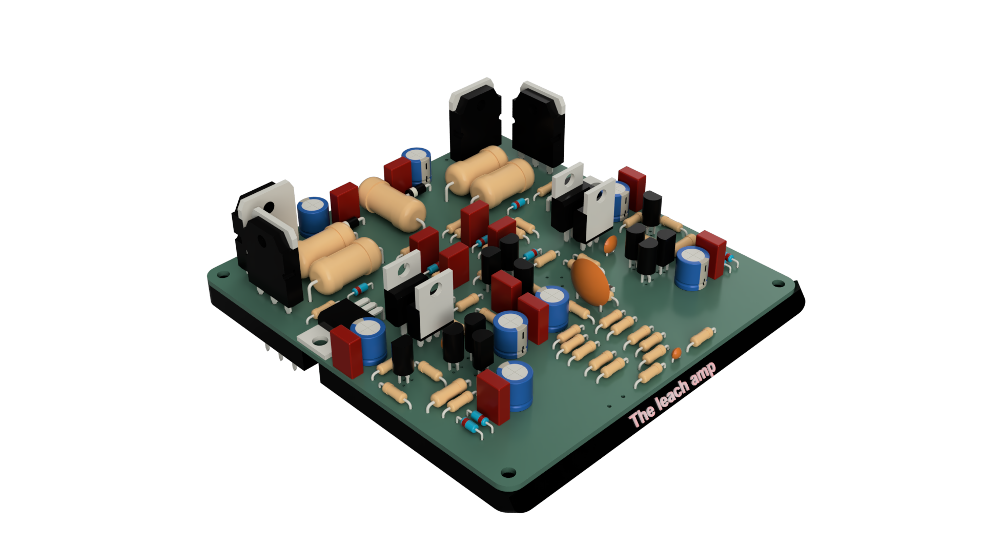
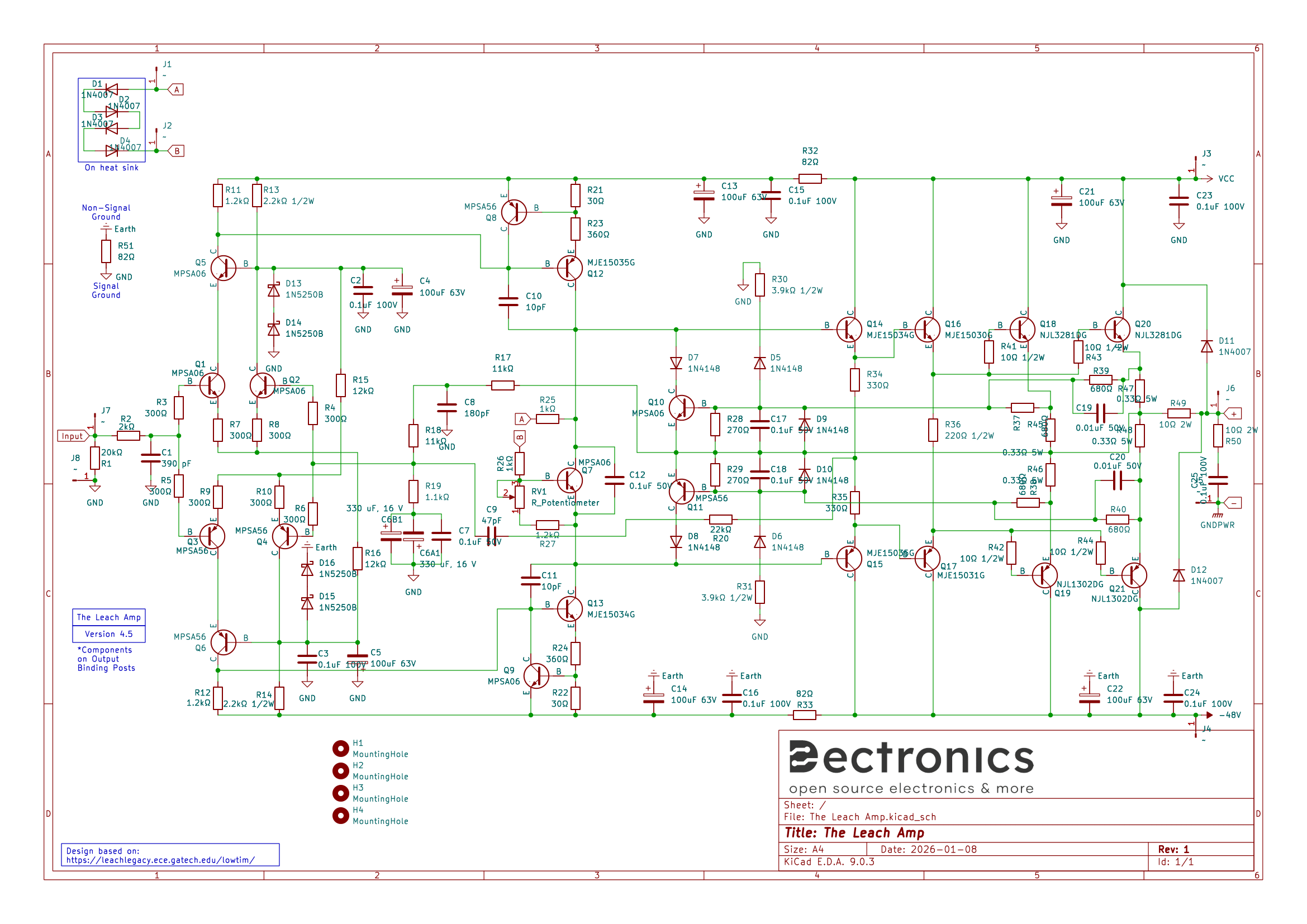
This is a complete pcb and schematic of the Leach Amp based on: https://leachlegacy.ece.gatech.edu/lowtim/
The Leach Amp is an open-source printed circuit board by TiebeDeclercq, from the TiebeDeclercq/Leach-Amp repository on GitHub, published under the MIT licence. It is a 2-layer board of 107.1 × 101.7 mm with 122 parts on 62 nets, routed with 634 tracks and 1 via.
It is built around the MPSA06, MPSA56 and 1N5250B, with the MJE15034G, MJE15035G and MJE15030G-JSM among its other parts. Its parts include 50 resistors, 25 capacitors, 21 transistors, 12 diodes and 8 connectors. It belongs with the audio and music boards of this library.


This is a complete pcb and schematic of the Leach Amp based on: https://leachlegacy.ece.gatech.edu/lowtim/
Het schematic is:
| Qty | Value | Footprint | References |
|---|---|---|---|
| 8 | 300Ω | Resistor_THT:R_Axial_DIN0207_L6.3mm_D2.5mm_P10.16mm_Horizontal | R3, R4, R5, R6, R7, R8, R9, R10 |
| 8 | ~ | TestPoint:TestPoint_THTPad_D2.0mm_Drill1.0mm | J1, J2, J3, J4, J5, J6, J7, J8 |
| 6 | 0.1uF 100V | Capacitor_THT:C_Rect_L7.0mm_W3.5mm_P5.00mm | C2, C3, C15, C16, C23, C24 |
| 6 | 100uF 63V | Capacitor_THT:CP_Radial_D8.0mm_P3.50mm | C4, C5, C13, C14, C21, C22 |
| 6 | 1N4148 | Diode_THT:D_DO-35_SOD27_P7.62mm_Horizontal | D5, D6, D7, D8, D9, D10 |
| 6 | MPSA06 | DectronicsFootprints:TO-92L_HandSolder_NPN | Q1, Q2, Q5, Q7, Q9, Q10 |
| 5 | MPSA56 | DectronicsFootprints:TO-92L_HandSolder_NPN | Q3, Q4, Q6, Q8, Q11 |
| 4 | 0.1uF 50V | Capacitor_THT:C_Rect_L7.0mm_W3.5mm_P5.00mm | C7, C12, C17, C18 |
| 4 | 0.33Ω 5W | Resistor_THT:R_Axial_DIN0918_L18.0mm_D9.0mm_P22.86mm_Horizontal | R45, R46, R47, R48 |
| 4 | 10Ω 1/2W | Resistor_THT:R_Axial_DIN0207_L6.3mm_D2.5mm_P10.16mm_Horizontal | R41, R42, R43, R44 |
| 4 | 1N5250B | Diode_THT:D_DO-35_SOD27_P7.62mm_Horizontal | D13, D14, D15, D16 |
| 4 | 680Ω | Resistor_THT:R_Axial_DIN0207_L6.3mm_D2.5mm_P10.16mm_Horizontal | R37, R38, R39, R40 |
| 4 | MountingHole | MountingHole:MountingHole_3.2mm_M3 | H1, H2, H3, H4 |
| 3 | 1.2kΩ | Resistor_THT:R_Axial_DIN0207_L6.3mm_D2.5mm_P10.16mm_Horizontal | R11, R12, R27 |
| 3 | 82Ω | Resistor_THT:R_Axial_DIN0207_L6.3mm_D2.5mm_P10.16mm_Horizontal | R32, R33, R51 |
| 2 | 0.01uF 50V | Capacitor_THT:C_Rect_L7.0mm_W3.5mm_P5.00mm | C19, C20 |
| 2 | 10pF | Capacitor_THT:C_Disc_D5.0mm_W2.5mm_P2.50mm | C10, C11 |
| 2 | 11kΩ | Resistor_THT:R_Axial_DIN0207_L6.3mm_D2.5mm_P10.16mm_Horizontal | R17, R18 |
| 2 | 12kΩ | Resistor_THT:R_Axial_DIN0207_L6.3mm_D2.5mm_P10.16mm_Horizontal | R15, R16 |
| 2 | 1N4007 | Diode_THT:D_DO-41_SOD81_P10.16mm_Horizontal | D11, D12 |
| 2 | 1kΩ | Resistor_THT:R_Axial_DIN0207_L6.3mm_D2.5mm_P10.16mm_Horizontal | R25, R26 |
| 2 | 2.2kΩ 1/2W | Resistor_THT:R_Axial_DIN0309_L9.0mm_D3.2mm_P12.70mm_Horizontal | R13, R14 |
| 2 | 270Ω | Resistor_THT:R_Axial_DIN0207_L6.3mm_D2.5mm_P10.16mm_Horizontal | R28, R29 |
| 2 | 3.9kΩ 1/2W | Resistor_THT:R_Axial_DIN0207_L6.3mm_D2.5mm_P10.16mm_Horizontal | R30, R31 |
| 2 | 30Ω | Resistor_THT:R_Axial_DIN0207_L6.3mm_D2.5mm_P10.16mm_Horizontal | R21, R22 |
| 2 | 330 uF, 16 V | Capacitor_THT:CP_Radial_D8.0mm_P3.50mm | C6A1, C6B1 |
| 2 | 330Ω | Resistor_THT:R_Axial_DIN0207_L6.3mm_D2.5mm_P10.16mm_Horizontal | R34, R35 |
| 2 | 360Ω | Resistor_THT:R_Axial_DIN0207_L6.3mm_D2.5mm_P10.16mm_Horizontal | R23, R24 |
| 2 | MJE15034G | DectronicsFootprints:TO-220-3_Vertical_B | Q13, Q14 |
| 2 | MJE15035G | DectronicsFootprints:TO-220-3_Vertical_B | Q12, Q15 |
| 2 | NJL1302DG | Package_TO_SOT_THT:TO-3P-3_Vertical | Q19, Q21 |
| 2 | NJL3281DG | Package_TO_SOT_THT:TO-3P-3_Vertical | Q18, Q20 |
| 1 | 1.1kΩ | Resistor_THT:R_Axial_DIN0207_L6.3mm_D2.5mm_P10.16mm_Horizontal | R19 |
| 1 | 10Ω 2W | Resistor_THT:R_Axial_DIN0922_L20.0mm_D9.0mm_P25.40mm_Horizontal | R49 |
| 1 | 180pF | Capacitor_SMD:C_0805_2012Metric_Pad1.18x1.45mm_HandSolder | C8 |
| 1 | 20kΩ | Resistor_THT:R_Axial_DIN0207_L6.3mm_D2.5mm_P10.16mm_Horizontal | R1 |
| 1 | 220Ω 1/2W | Resistor_THT:R_Axial_DIN0207_L6.3mm_D2.5mm_P10.16mm_Horizontal | R36 |
| 1 | 22kΩ | Resistor_THT:R_Axial_DIN0207_L6.3mm_D2.5mm_P10.16mm_Horizontal | R20 |
| 1 | 2kΩ | Resistor_THT:R_Axial_DIN0207_L6.3mm_D2.5mm_P10.16mm_Horizontal | R2 |
| 1 | 390 pF | Capacitor_THT:C_Disc_D3.0mm_W2.0mm_P2.50mm | C1 |
| 1 | 47pF | Capacitor_THT:C_Disc_D12.5mm_W5.0mm_P7.50mm | C9 |
| 1 | LOGO | Drawings_Customs:Dectronics_Sub_20mm | G*** |
| 1 | MJE15030G | DectronicsFootprints:TO-220-MJE15030 | Q16 |
| 1 | MJE15031G | DectronicsFootprints:TO-220-MJE15030 | Q17 |
| 1 | R_Potentiometer | Potentiometer_THT:Potentiometer_Bourns_3386P_Vertical | RV1 |
X-ANONYMOUS-POWER-AMPLIFIER/X-B350W-4-LITE
SIMPLIFIED MAIN-CIRCUIT MODULE OF 350 WATTS CLASS-B AUDIO POWER AMPLIFIER MAIN-CIRCUIT FOR 4-OHMS OUTPUT LOAD


chdsolinap/ece-projects
ECE hardware and electronics projects — PCB design, circuit prototypes, and embedded systems built at PLM.

hackclub/OnBoard
💡 Join 1,000 teenagers and make your first PCB with a $100 grant!

SensorsIot/SuperPower
Here you should find the best power supplies for your low-power projects

TweetyDaBird/Lotus-58-Classic
A split ergo linear keyboard derived from the Lily58 family


tebl/BulkyMIDI-32
A HW build of the MT32-PI project, allowing you to emulate a Roland MT-32 using a Raspberry Pi. Includes enough additional modules to build a MIDI-mountain as well as adapters for connecting to most things retro.
It measures 107.1 × 101.7 mm and has 2 copper layers, 1.6 mm thick.
122 parts, built around the MPSA06, MPSA56, 1N5250B and MJE15034G. The full list of its parts is on this page, with links to each part's symbol and footprint where PCBKit's library has them.
From the TiebeDeclercq/Leach-Amp repository on GitHub, at the commit this page was made from: the board is The Leach Amp PCB/The Leach Amp.kicad_pcb and its schematic The Leach Amp PCB/The Leach Amp.kicad_sch. PCBKit opens the board in the browser, with nothing to install.
Its repository publishes it under the MIT licence: you may reuse it on that licence's terms (keep the author's notice, and for a copyleft licence share your changes alike).