2 layers50 × 100 mm
Re innovation minipredictionmachine minipredictionmachine wifi unit
oomlout/oomlout_oomp_project_bot_v_2
30 parts

 ThomasStolt/Junior-Stair-Light-Project
This is a smaller/easier/cheaper version of my NeoPixel Stair Light Project. The basic idea is to use a bunch of cheap 12V LEDs stripes attached to your indoor stairs, two IR sensors and an Arduino Nano and animate…
Junior Stair Light Project is an open-source printed circuit board by ThomasStolt, from the ThomasStolt/Junior-Stair-Light-Project repository on GitHub. It is a 2-layer board of 90 × 90 mm with 107 parts on 121 nets, routed with 618 tracks and 1 via.
It is built around the L4940V5, BC327 and BC337, with the MH3 and MH4 among its other parts. Its parts include 56 resistors, 6 connectors, 3 capacitors and 2 ICs. It belongs with the AVR (ATmega, ATtiny) boards of this library.


This is a smaller/easier/cheaper version of my NeoPixel Stair Light Project. The basic idea is to use a bunch of cheap 12V LEDs stripes attached to your indoor stairs, two IR sensors and an Arduino Nano and animate those LED stripes if a person is walking up or down the stairs.
I created this for a friend of mine. He went out on the internet and bought sets of LED stripes (originally thought for cars, 12V) and mounted them under the stairs. I then went ahead and created this little project around it, giving it some more fun.
For several reasons, all grounds of the LED stripes were connected together and all the positive leads were routed to the circuit for switching/PWM. Because of that, I had to use that dual-transistor circuit, which I found on the internet, to be able to switch the positive lines. It is actually easier to switch the negative lines, that just requires one transistor/MOSFET, so if you do this and you have a choice, you should probably go with that approach.
Nothing more to add really, just read the circuit under schematics/kicad (there is a PDF) and you should be good.
Then per step you need:
Additionally you need a prototype board (or the PCB, see below) for soldering components, some wires for connecting the components, tools (soldering iron, solder, cutter, clippers, a Dremel helps to cut the copper on the board) and some time and patience.
I have created a first "Release Candidate" (RC) of a printed circuit board for this project. I added the maximum number of channels (steps) that an Arduino Nano can have, which is number of Digital outputs + number of Analog outputs - 2 analog outputs (for the IR sensors), which should end up at 18.
So, 18 is the maximum number of steps your stairs can have using this single Arduino Nano module. If you have less stairs, just populate the board with the appropriate number of parts for the channels. If you have more stairs - well, you are on your own.
To order the PCB you'll need to send/upload the Gerber files to a PCB manufacturer of your choice. You can find the Gerber files here: Gerbes, just use the ZIP archive. The board is 9cm x 9cm, currently you get special offers for 2$ for 10 pieces - ridicolous!
As of today (Sep 2018), I have not yet ordered a PCB, so I cannot say whether this PCB is really working, it might still be full of bugs! Try at your own risk!
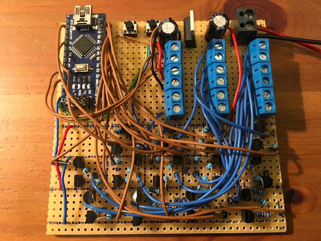 This is the finished board, top view.
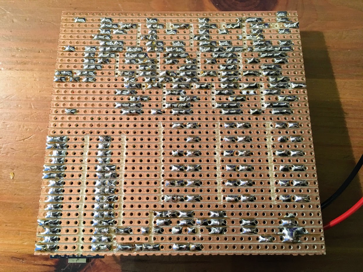 This is the finished board on a prototype PCB, bottom view.
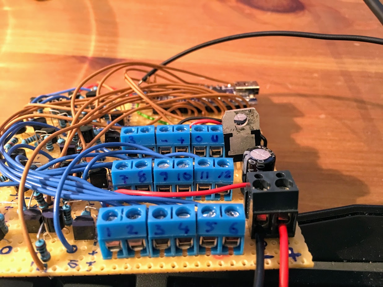 These are the connectors for the LED strips, power and IR sensors
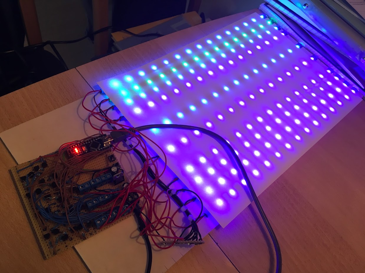 The test setup for finishing the code.
I did not have enough left over stripes, hence there are some missing here, but that is sufficient.
This can probably be done on one weekend if you are somewhat experienced.
| Qty | Value | Footprint | References |
|---|---|---|---|
| 36 | 1k | Resistors_THT:R_Axial_DIN0207_L6.3mm_D2.5mm_P7.62mm_Horizontal | R10_2, R10_3, R11_2, R11_3, R12_2, R12_3, R13_2, R13_3, R14_2, R14_3, R15_2, R15_3, R16_2, R16_3, R17_2, R17_3 +20 |
| 20 | 10k | Resistors_THT:R_Axial_DIN0207_L6.3mm_D2.5mm_P7.62mm_Horizontal | R1, R1_1, R2, R2_1, R3_1, R4_1, R5_1, R10_1, R11_1, R12_1, R13_1, R14_1, R15_1, R16_1, R17_1, R18_1 +4 |
| 18 | BC327 | TO_SOT_Packages_THT:TO-92_Inline_Narrow_Oval | T1_2, T2_2, T3_2, T4_2, T5_2, T6_2, T7_2, T10_2, T11_2, T12_2, T13_2, T14_2, T15_2, T16_2, T17_2, T18_2 +2 |
| 18 | BC337 | TO_SOT_Packages_THT:TO-92_Inline_Narrow_Oval | T1_1, T2_1, T3_1, T4_1, T5_1, T6_1, T7_1, T10_1, T11_1, T12_1, T13_1, T14_1, T15_1, T16_1, T17_1, T18_1 +2 |
| 3 | Conn_01x06 | Connectors_JST:JST_XH_B06B-XH-A_06x2.50mm_Straight | J2, J5, J6 |
| 2 | 100uF | Capacitors_THT:CP_Radial_D7.5mm_P2.50mm | C1, C2 |
| 2 | CONN_01X03 | Connectors_JST:JST_XH_B03B-XH-A_03x2.50mm_Straight | J3, J4 |
| 1 | 100nF | Capacitors_THT:C_Disc_D3.8mm_W2.6mm_P2.50mm | C3 |
| 1 | 12V Eingang | Connectors_JST:JST_XH_B02B-XH-A_02x2.50mm_Straight | J1 |
| 1 | Arduino_Nano | NOKO_Wetimer:Arduino_Nano | U2 |
| 1 | L4940V5 | TO_SOT_Packages_THT:TO-220_Vertical | U1 |
| 1 | MH1 | Mounting_Holes:MountingHole_3.2mm_M3_DIN965_Pad | MH1 |
| 1 | MH2 | Mounting_Holes:MountingHole_3.2mm_M3_DIN965_Pad | MH2 |
| 1 | MH3 | Mounting_Holes:MountingHole_3.2mm_M3_DIN965_Pad | MH3 |
| 1 | MH4 | Mounting_Holes:MountingHole_3.2mm_M3_DIN965_Pad | MH4 |
oomlout/oomlout_oomp_project_bot_v_2

carlos-jenkins/relay-shield
Relay and current sensor shield for Spark Core


jackhumbert/reform
This is the main repository for the MNT Reform open source laptop.

RonishNadar/open-01
OPEN-01 - Omnidirectional Perception & Embedded Navigation. An open-source, low-cost ROS2 robot platform.


ncssrtnvnthm/WATCH2026-theremin
Theremin project for the 2026 WATCH program
It measures 90 × 90 mm and has 2 copper layers, 1.6 mm thick.
107 parts, built around the L4940V5, BC327, BC337 and MH3. The full list of its parts is on this page, with links to each part's symbol and footprint where PCBKit's library has them.
From the ThomasStolt/Junior-Stair-Light-Project repository on GitHub, at the commit this page was made from: the board is schematics/kicad/Junior-Stair-Light-Project.kicad_pcb. PCBKit opens the board in the browser, with nothing to install.
Its repository states no licence, so its author keeps all rights: ask ThomasStolt before reusing the design.