2 layers205.7 × 236.9 mm
 The-Invent0r/6502-Computer-PCB31
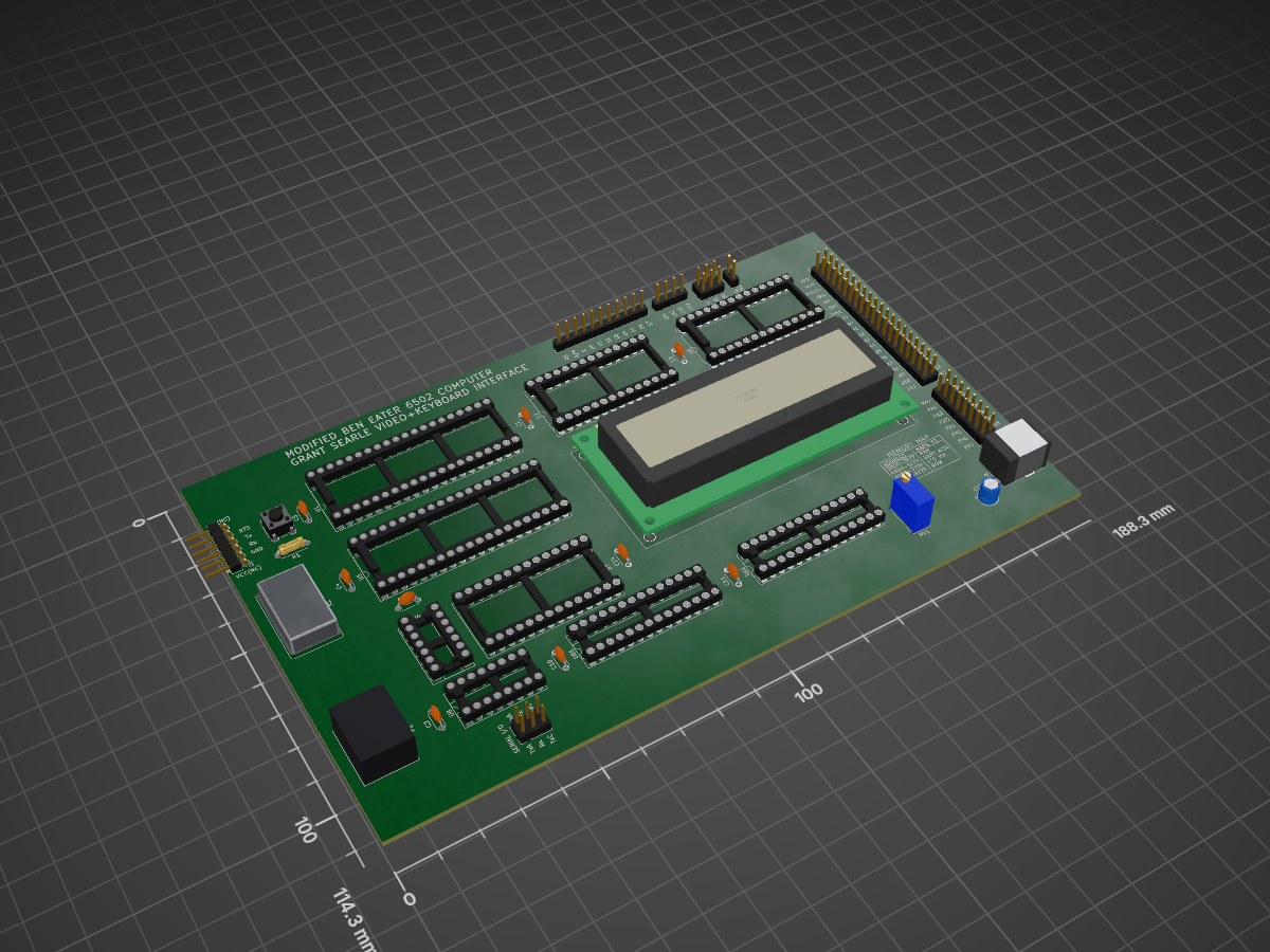
These are the PCB files for the modified BE6502 computer I put together.
6502 Computer is an open-source printed circuit board by The-Invent0r, from the The-Invent0r/6502-Computer-PCB repository on GitHub. It is a 2-layer board of 188.3 × 114.3 mm with 34 parts on 160 nets.
It is built around the ATMEGA328P-PU, 74HC00D and 74HC166D, with the ACO-18.432MHZ-EK among its other parts. Its parts include 10 capacitors, 10 connectors, 8 ICs, 1 resistor and 1 switch. It belongs with the retro computing and games boards and the AVR (ATmega, ATtiny) boards of this library.


DISCLAIMER: I DELETED ALL OF THE CONNECTIONS FOR GRANT SEARLE'S VIDEO+KEYBOARD INTERFACE BEFORE UPLOADING THE FILES. IF YOU WANT TO ADD IN THE VIDEO+KEYBOARD INTERFACE PLEASE TAKE A LOOK AT HIS WEBSITE (http://searle.x10host.com/MonitorKeyboard/index.html) AND FOLLOW THE DIRECTIONS ON THERE. IT MIGHT BE WORTH IT TO PROTOTYPE THE INTERFACE ON BREADBOARDS FIRST.
I made this Modified version of Ben Eater's 6502 computer PCB and decided instead of adding a VGA video card, I wanted to connect this to a CRT monitor using a composite video cable. I decided to add in a 6551 ACIA (Asyncronous Communications Interface Adapter) to give the computer serial I/O capabilites. I then found Grant Searle's video+keyboard interface and decided to incorporate that into my design. The only issue was that my 6551 was sending and receiving data at 19200 baud, and the video+keyboard interface was running at 115200 baud. Luckily it was an easy fix to go into the software and update the USART_BAUD variable from 115200u1 to 19200u1. However, before uploading the code I changed the fuse bytes to ensure that the 2 AVR chips were running at the correct crystal oscillator frequencies. To upload the code for the keyboard chip I used WinAVR. I found that before uploading the keyboard interface code, I needed to change the file name to main.c and I also had to create my own makefile for the atmega328p. For the video chip I decided to use the .hex file, and burn that directly into the other atmega328p using the command line. When I first prototyped this circuit on breadboards I had a lot of issues which I later discovered were caused by using a low quality breadboard. So if all off your connections and software are correct, try using a more expensive but higher quality BB830 breadboard. When you first connect the circuit to an LCD monitor or CRT monitor you should see a cursor blinking. In order to conduct a loopback test of the circuit, simply connect the Rx pin to the Tx pin on the keyboard chip, then connect the PS2 keyboard and start typing. If it works then you'll see the correct characters on the screen.
I also made a YouTube video briefly documenting my progress and demonstrating the workings of the computer. (https://youtu.be/8I7XNCFC5iU)


| Qty | Value | Footprint | References |
|---|---|---|---|
| 8 | 0.1uF | Capacitor_THT:C_Disc_D4.3mm_W1.9mm_P5.00mm | C1, C2, C3, C4, C10, C11, C12, C14 |
| 2 | ATmega328P-PU | Package_DIP:DIP-28_W7.62mm_Socket_LongPads | UA1, UB1 |
| 2 | Conn_02x03_Odd_Even | Connector_PinHeader_2.54mm:PinHeader_2x03_P2.54mm_Vertical | J4, J7 |
| 1 | 0.1 | Capacitor_THT:C_Disc_D4.3mm_W1.9mm_P5.00mm | C5 |
| 1 | 10uF | Capacitor_THT:CP_Radial_D5.0mm_P2.00mm | C15 |
| 1 | 1K | Resistor_THT:R_Axial_DIN0207_L6.3mm_D2.5mm_P7.62mm_Horizontal | R1 |
| 1 | 28C256 | Package_DIP:DIP-28_W15.24mm_Socket_LongPads | U2 |
| 1 | 6551 | Package_DIP:DIP-28_W15.24mm_Socket_LongPads | U7 |
| 1 | 74HC00 | Package_DIP:DIP-14_W7.62mm_Socket_LongPads | U4 |
| 1 | 74HC166 | Package_DIP:DIP-16_W7.62mm_Socket_LongPads | U8 |
| 1 | ACO-1.8432MHz | Oscillator:Oscillator_DIP-14 | X1 |
| 1 | Barrel_Jack | Connector_BarrelJack:BarrelJack_CUI_PJ-063AH_Horizontal | J8 |
| 1 | CY62256-70PC | Package_DIP:DIP-28_W15.24mm_Socket_LongPads | U6 |
| 1 | Conn_01x04_Male | Connector_PinHeader_2.54mm:PinHeader_1x04_P2.54mm_Vertical | J3 |
| 1 | Conn_01x06_Male | Connector_PinHeader_2.54mm:PinHeader_1x06_P2.54mm_Horizontal | J6 |
| 1 | Conn_01x11_Male | Connector_PinHeader_2.54mm:PinHeader_1x11_P2.54mm_Vertical | J9 |
| 1 | Conn_02x01 | Connector_PinHeader_2.54mm:PinHeader_2x01_P2.54mm_Vertical | J10 |
| 1 | Conn_02x08_Odd_Even | Connector_PinHeader_2.54mm:PinHeader_2x08_P2.54mm_Vertical | J5 |
| 1 | Conn_02x20_Odd_Even | Connector_PinHeader_2.54mm:PinHeader_2x20_P2.54mm_Vertical | J2 |
| 1 | Mini-DIN_6pins | ps2:Connector_Mini-DIN_Female_6Pin_2rows | P1 |
| 1 | RESET | Button_Switch_THT:SW_PUSH_6mm_H5mm | SW1 |
| 1 | R_POT_TRIM_US | Potentiometer_THT:Potentiometer_Bourns_3386C_Horizontal | RV1 |
| 1 | WC1602A | Display:WC1602A | U3 |
| 1 | WD65C02 | Package_DIP:DIP-40_W15.24mm_Socket_LongPads | U1 |
| 1 | WD65C22 | Package_DIP:DIP-40_W15.24mm_Socket_LongPads | U5 |

slu4coder/Minimal-UART-Computer-1-2
Legacy: Version 1 and 2 of my TTL-only CPU featuring UART I/O, an expansion port, 512KB SSD at up to 10MHz clock speed


slu4coder/Minimal-64x4-Home-Computer
My DIY TTL home computer with VGA and PS/2 and 4x the processing power of a Commodore C64 or Apple II.

slu4coder/Minimal-64-Home-Computer
Legacy: Full TTL-only home computer with VGA and PS/2 and twice the processing power of a Commodore 64


It measures 188.3 × 114.3 mm and has 2 copper layers, 1.6 mm thick.
34 parts, built around the ATMEGA328P-PU, 74HC00D, 74HC166D and ACO-18.432MHZ-EK. The full list of its parts is on this page, with links to each part's symbol and footprint where PCBKit's library has them.
From the The-Invent0r/6502-Computer-PCB repository on GitHub, at the commit this page was made from: the board is KiCAD Schematics/6502 Computer.kicad_pcb. PCBKit opens the board in the browser, with nothing to install.
Its repository states no licence, so its author keeps all rights: ask The-Invent0r before reusing the design.