2 layers68.6 × 53.3 mm

 ThatGuyCodes605/TGC-Core-328P-v1
A Arduino Uno Style board based around the ATMega-328P microcontroller
TGC Core devboard Mega v1 is an open-source printed circuit board by ThatGuyCodes605, from the ThatGuyCodes605/TGC-Core-328P-v1 repository on GitHub, published under the GPL-3.0 licence. It is a 4-layer board of 48.3 × 55.7 mm with 28 parts on 44 nets, routed with 456 tracks and 59 vias.
It is built around the ATMEGA328P-PU, CH340C and AMS1117-5.0. Its parts include 11 capacitors, 3 resistors, 3 ICs, 3 connectors and 1 diode. It belongs with the microcontroller boards boards and the AVR (ATmega, ATtiny) boards of this library.


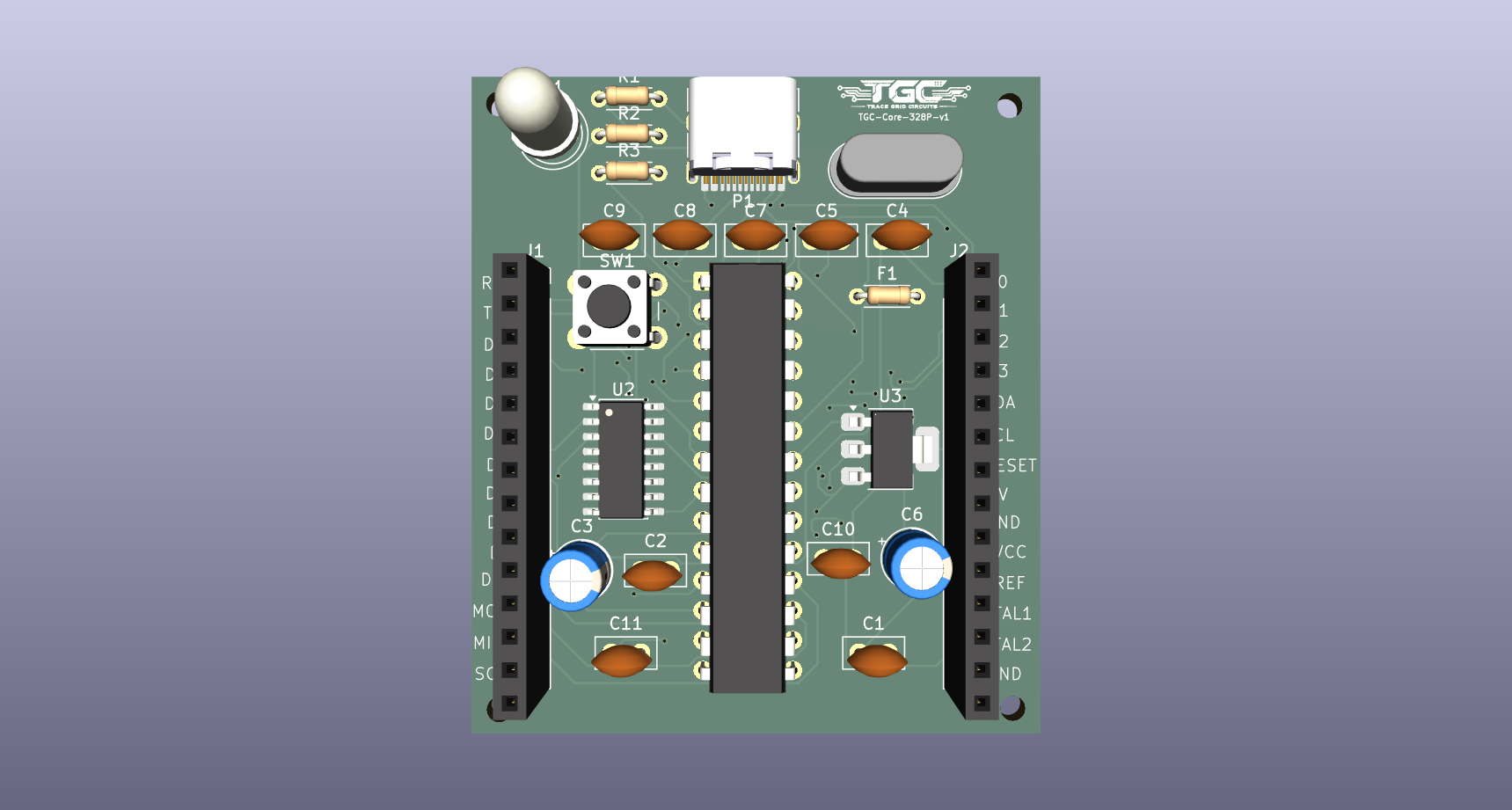
The TGC-Core-328P-v1 is an open-source hardware development board. Based on the file naming and standard conventions, it is designed around the "Mega" architecture (typically the Microchip ATme[...]
This repository contains the complete set of KiCad EDA files necessary to view, modify and manufacture the printed circuit board (PCB).
The project is entirely self-contained within the following KiCad design files:
| File Name | Description |
|---|---|
TGC-Core-devboard-Mega-v1.kicad_pro | The main KiCad Project file. Open this file to load the entire project space. |
TGC-Core-devboard-Mega-v1.kicad_sch | The Schematic file. Contains the logical connections, components (like the USB-C plug and SW_Push buttons), and wiring. |
TGC-Core-devboard-Mega-v1.kicad_pcb | The PCB Layout file. Contains the physical board routing, copper layers, and silkscreen definitions. |
TGC-Core-devboard-Mega-v1.png | A visual render or top-down image of the board design. |
Based on standard Mega-compatible board parameters:
To view or modify the hardware design:
TGC-Core-devboard-Mega-v1.kicad_pro file.Because this board shares the Mega architecture, it is fully compatible with the standard Arduino ecosystem:
This hardware design and its accompanying documentation are licensed under the GNU General Public License v3.0 (GPL-3.0-or-later).
Summary of your rights under GPLv3:
For the full legal text, see the GNU licenses page: https://www.gnu.org/licenses/gpl-3.0.html
Note: To make the change complete, consider adding a LICENSE file containing the full GPLv3 text and an explicit copyright line (for example: "Copyright (c) 2026 ThatGuyCodes605"). I can add that file for you if you want.
| Qty | Value | Footprint | References |
|---|---|---|---|
| 7 | 100nF | Capacitor_THT:C_Disc_D5.0mm_W2.5mm_P2.50mm | C1, C4, C5, C7, C8, C9, C11 |
| 2 | 10µF | Capacitor_THT:CP_Radial_D5.0mm_P2.00mm | C3, C6 |
| 2 | 22pF | Capacitor_THT:C_Disc_D5.0mm_W2.5mm_P2.50mm | C2, C10 |
| 2 | Conn_01x14 | Connector_PinSocket_2.54mm:PinSocket_1x14_P2.54mm_Vertical | J1, J2 |
| 1 | 10k | Resistor_THT:R_Axial_DIN0204_L3.6mm_D1.6mm_P5.08mm_Horizontal | R2 |
| 1 | 16MHz | Crystal:Crystal_HC49-4H_Vertical | Y1 |
| 1 | 330Ω | Resistor_THT:R_Axial_DIN0204_L3.6mm_D1.6mm_P5.08mm_Horizontal | R3 |
| 1 | 5.1K | Resistor_THT:R_Axial_DIN0204_L3.6mm_D1.6mm_P5.08mm_Horizontal | R1 |
| 1 | 500mA | Resistor_THT:R_Axial_DIN0204_L3.6mm_D1.6mm_P5.08mm_Horizontal | F1 |
| 1 | AMS1117-5.0 | Package_TO_SOT_SMD:SOT-223-3_TabPin2 | U3 |
| 1 | ATmega328P-P | Package_DIP:DIP-28_W7.62mm | U1 |
| 1 | CH340C | Package_SO:SOIC-16_3.9x9.9mm_P1.27mm | U2 |
| 1 | GREEN | LED_THT:LED_D5.0mm_Clear | D1 |
| 1 | SW_Push | Button_Switch_THT:SW_PUSH_6mm | SW1 |
| 1 | USB_C_Plug_USB2.0 | Connector_USB:USB_C_Receptacle_HRO_TYPE-C-31-M-12 | P1 |
The 24 most common of 28 parts.

zatelectronic/ZATINO_PTH_V2
O microcontrolador principal é o clássico ATmega328P-PU no encapsulamento DIP-28, encaixado diretamente na placa.


shawnsony07/smart-grid-fault-detector
An ATmega328P-based smart grid fault detector featuring high-side current sensing via INA180A1 and voltage monitoring.


It measures 48.3 × 55.7 mm and has 4 copper layers, 1.6 mm thick.
28 parts, built around the ATMEGA328P-PU, CH340C and AMS1117-5.0. The full list of its parts is on this page, with links to each part's symbol and footprint where PCBKit's library has them.
From the ThatGuyCodes605/TGC-Core-328P-v1 repository on GitHub, at the commit this page was made from: the board is TGC-Core-devboard-Mega-v1.kicad_pcb and its schematic TGC-Core-devboard-Mega-v1.kicad_sch. PCBKit opens the board in the browser, with nothing to install.
Its repository publishes it under the GPL-3.0 licence: you may reuse it on that licence's terms (keep the author's notice, and for a copyleft licence share your changes alike).