

4 layers120 × 113 mm
Voron Klipper Board
VoronDesign/Voron-Hardware
Cool Hardware designed by the Voron Design group
360 parts1.1kGPL-3.0

A through-hole PCB conversion of HAGIWO's 6 channel eurorack gate sequencer. Includes Gerbers, Code and building instructions.
Main pcb is an open-source printed circuit board by Testbild-synth, from the Testbild-synth/Hagiwo_009_030_sequencer repository on GitHub, published under the MIT licence. It is a 2-layer board of 29 × 99.8 mm with 26 parts on 23 nets, routed with 163 tracks and 35 vias.
It is built around the BAT43. Its parts include 10 resistors, 7 connectors, 3 capacitors and 2 diodes. It belongs with the audio and music boards of this library.
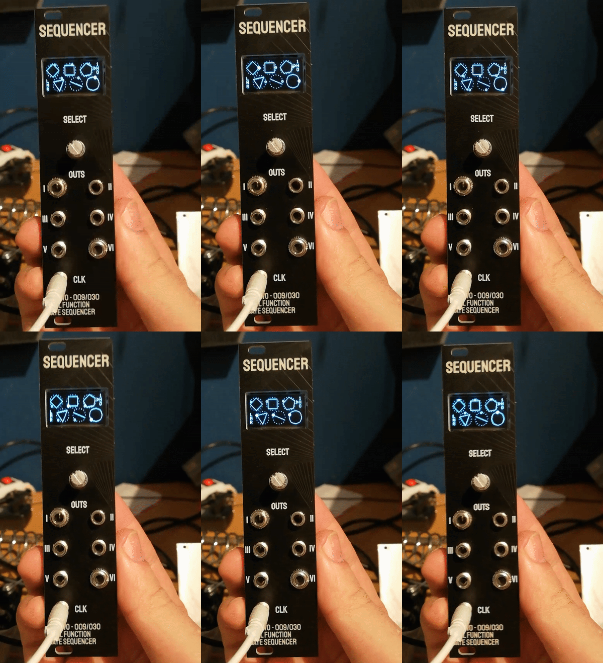
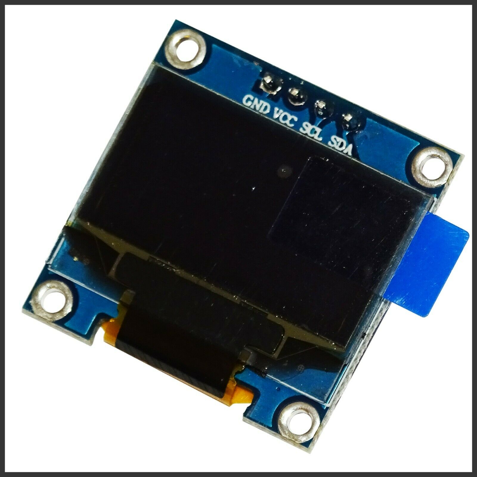
This project is a through hole PCB version the HAGIWO 009 six channel gate sequencer and 030 euclidean rythm sequencer eurorack synth modules. the modules run on an Arduino Nano and uses a 0.96 inch Oled I2C Display. The exact brand is not important, just make sure it is 128/64 pixels and has an SSD1306 driver. Also, pinout should match the one specified on the PCB: I saw that there are some modules that have VCC-GND-SCL-SDA, but we need GND-VCC-SCL-SDA
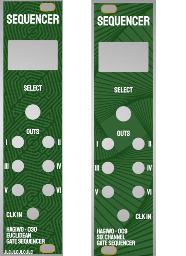
 Since both modules use the same hardware, I made it so that the panel pcb is flippable to reflect both functions.
You can find the schematic and BOM in the root folder. For the PCBs, the module has one circuit PCB and one panel PCB. You can order them on any common PCB manufacturing service, I used JLCPCB. Standard settings should be fine, but if you have exposed copper on the panel you should go with a lead free surface finish (ENIG/Leadfree HASL).
If the panel sizes are not recognized correctly (may happen with my export sometimes) just put 128.5x30.
Use the panel_pcb.zip gerbers if you want a panel with exposed solder mask (so silver letters for title) but then make sure to choose a lead free finish cause health reasons. If you don't want that, use the "panel_no_silver.zip" version.
The panel PCB is switchable to reflect the function depending on the firmware you want to use.
The PCB is relatively simple to build, all the components are through-hole soldering. It is easiest to start first with the resistors and capacitors, then the headers, and then the jacks at the end.
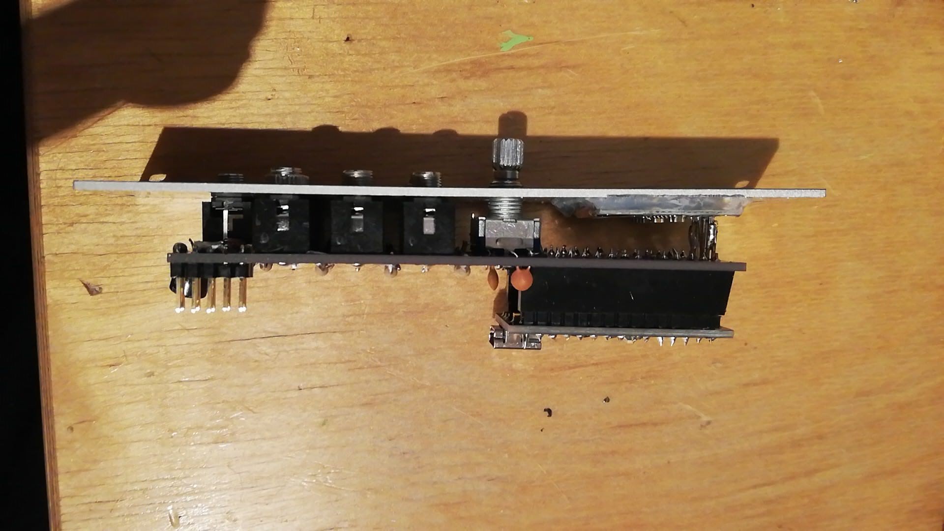
The only thing that is a bit tricky is the screen, since depending on your components it can stand out on the top. To prevent this, you can try soldering the display directly on the PCB.
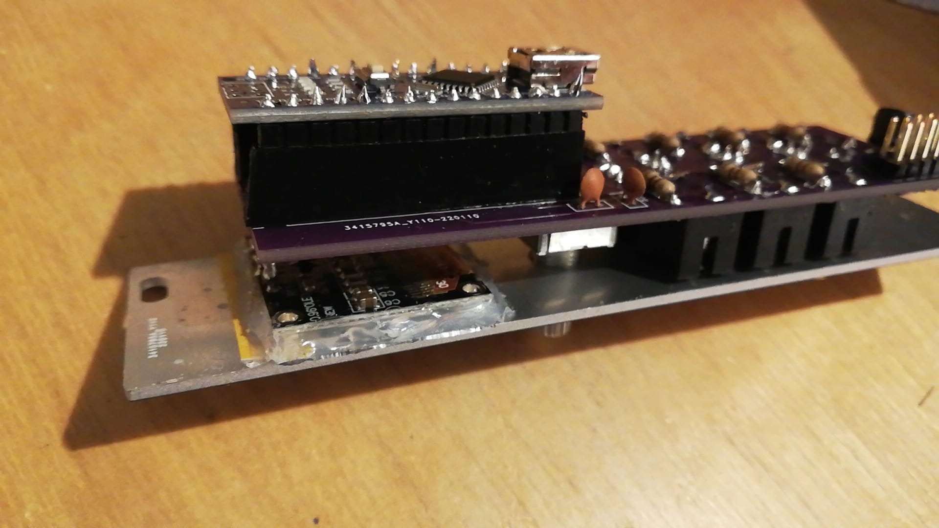
Another optional but good idea is glueing the screen to the panel first before mounting to ensure it is positioned directly behind the cutout. Downside to glueing is obviously not being able to flip the panel when flashing the firmware so only do it if you build two or are sure you dont need the other side of the panel.
There are three Arduino files included in this project:
You need the Adafruit_SSD1306 and encoder libraries. I also changed it such that is uses FastGPIO instead of DigitalRead (to recude latency, which was probably not a concern in the first place but I do it in all my arduino projects). See the FastGPIO repo.
One important change from HAGIWO's code is the introduction of the parameter ENCODER_COUNT_PER_ROTATION. Rotation encoders come in different versions, some have one click per rotation, some have two, others even have four. If you see multiple messages during a single turn while running the test_circuit file, set this parameter higher in all files before uploading.
For the six channel sequencer, there are preprogrammed pattern banks you can change (bnk1_ptn, bnk2_ptn, etc.). The patterns are in hexadecimal and represent 16 binary numbers. So for example if the number says 0x8888, this means 1000100010001000, meaning a four on the floor pattern. Use a hex to binary converter to help you convert it.
HAGIWO's version only updates the screen when the clock comes in, but I think this makes for a bad user experience so I changed it to update when you turn the encoder as well.
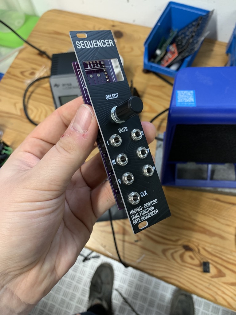
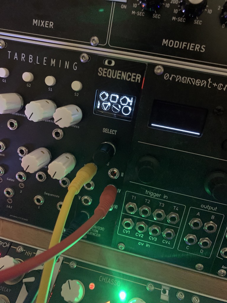
By Felix W.
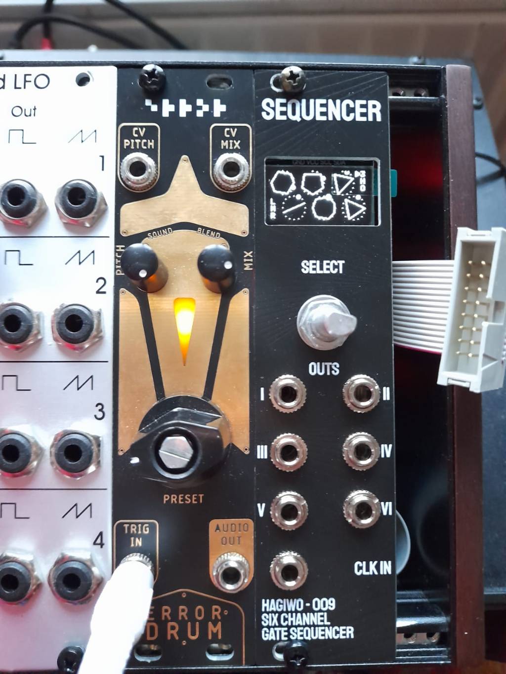
By Elija
| Qty | Value | Footprint | References |
|---|---|---|---|
| 7 | 2.2k | easyeda:R_AXIAL-0.3 | R1, R2, R3, R4, R5, R6, R9 |
| 2 | 10n | easyeda:RAD-0.1 | C1, C2 |
| 2 | 3k3 | easyeda:R_AXIAL-0.3 | R7, R8 |
| 2 | BAT43 | easyeda:D_DO-35_SOD27_P7.62MM_HORIZONTAL | D1, D2 |
| 1 | AutoGenerated:Pad_1.60mm | ||
| 1 | AutoGenerated:Pad_1.52mm | ||
| 1 | 100k | easyeda:R_AXIAL-0.3 | R10 |
| 1 | 10u | easyeda:CAP-D4.0×F1.5 | C3 |
| 1 | ALPS_ENCODER+PUSHSWITCHNORMAL | easyeda:ENCODER+SWITCH | 1 |
| 1 | CLK | easyeda:THONKICONN_1 | J7 |
| 1 | EURORACK_POWERHEADER_V2 | easyeda:EURORACK_POWER_V2 | EP1 |
| 1 | O1 | easyeda:THONKICONN_1 | J1 |
| 1 | O2 | easyeda:THONKICONN_1 | J3 |
| 1 | O3 | easyeda:THONKICONN_1 | J5 |
| 1 | O4 | easyeda:THONKICONN_1 | J6 |
| 1 | O5 | easyeda:THONKICONN_1 | J2 |
| 1 | O6 | easyeda:THONKICONN_1 | J4 |
VoronDesign/Voron-Hardware
Cool Hardware designed by the Voron Design group


ravinrabbid/DonCon2040
RP2040 based firmware and hardware for DIY Taiko no Tatsujin Drum Controllers

Testbild-synth/HAGIWO_arduino_oscillator
4HP through hole version of the HAGIWO FM/additive/chord oscillator with mode switch and gain input.

bvarner/pi485
An open-source TTL UART <-> RS485 converter, intended for a Raspberry Pi or Arduino

Testbild-synth/HAGIWO-029-033-Eurorack-quantizer
Through hole PCB version of the HAGIWO Dual Quantizer/SH101 Sequencer Eurorack Module-.

Testbild-synth/HAGIWO-005-Eurorack-sequencer
Through hole PCB version of the HAGIWO 005 Generative Sequencer Eurorack module.
It measures 29 × 99.8 mm and has 2 copper layers.
26 parts, built around the BAT43. The full list of its parts is on this page, with links to each part's symbol and footprint where PCBKit's library has them.
From the Testbild-synth/Hagiwo_009_030_sequencer repository on GitHub, at the commit this page was made from: the board is design files/pcb/main_pcb.kicad_pcb. PCBKit opens the board in the browser, with nothing to install.
Its repository publishes it under the MIT licence: you may reuse it on that licence's terms (keep the author's notice, and for a copyleft licence share your changes alike).