4 layers118.7 × 72.5 mm
Framework16-m2-cellular
Popax21/framework16-cellular
A M.2 cellular modem Expansion Bay module for the Framework Laptop 16
101 parts7GPL-3.0

 Terrails/FW16-OCuLink43
The schematic in itself is pretty simple. You only need to connect the TX and RX PCIe lanes to the correct pins of the OCuLink connector.
Fw16 oculink8i is an open-source printed circuit board by Terrails, from the Terrails/FW16-OCuLink repository on GitHub, published under the MIT licence. It is a 4-layer board of 119 × 73.9 mm with 55 parts on 129 nets, routed with 1,253 tracks and 387 vias.
It is built around the TL331LVDBV and BR24G32FVT-3GE2. Its parts include 35 resistors, 6 connectors, 5 capacitors, 3 ICs and 2 switches.


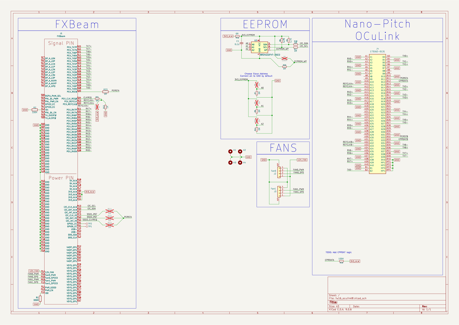
The schematic in itself is pretty simple. You only need to connect the TX and RX PCIe lanes to the correct pins of the OCuLink connector. And then add components such as the EEPROM that the Embedded Controller (EC) on the laptop reads to configure GPIO pins and bifurcation.
A pdf version of the schematic is available here.
As for the EEPROM, I have decided to use the same one that Framework is using in their Dual SSD reference design. The BR24G32FVT-3GE2. The chip is marked as not recommended for new design according to Mouser, but it still seems to be in stock, although it can easily be swapped with another if required.
The EEPROM's address pins are all connected to the ground as that is the address the EC expects and by default the write protection (WP) is disabled by being connected to GND to allow writing data to it.
For the fans I had to go with an alternative FPC header, as the one Framework uses on their boards was not available anywhere. The connector I use is slightly smaller, but still makes the connection nevertheless and the fans do spin up. I have specifically went with the AFC05-S04FIA-00 that is available on LCSC to use with JLCPCB's assembly.
The firmware file is generated using Framework's Expansion Bay tool. More info on the specific file I have been using in my testing and how I flashed it SOON.
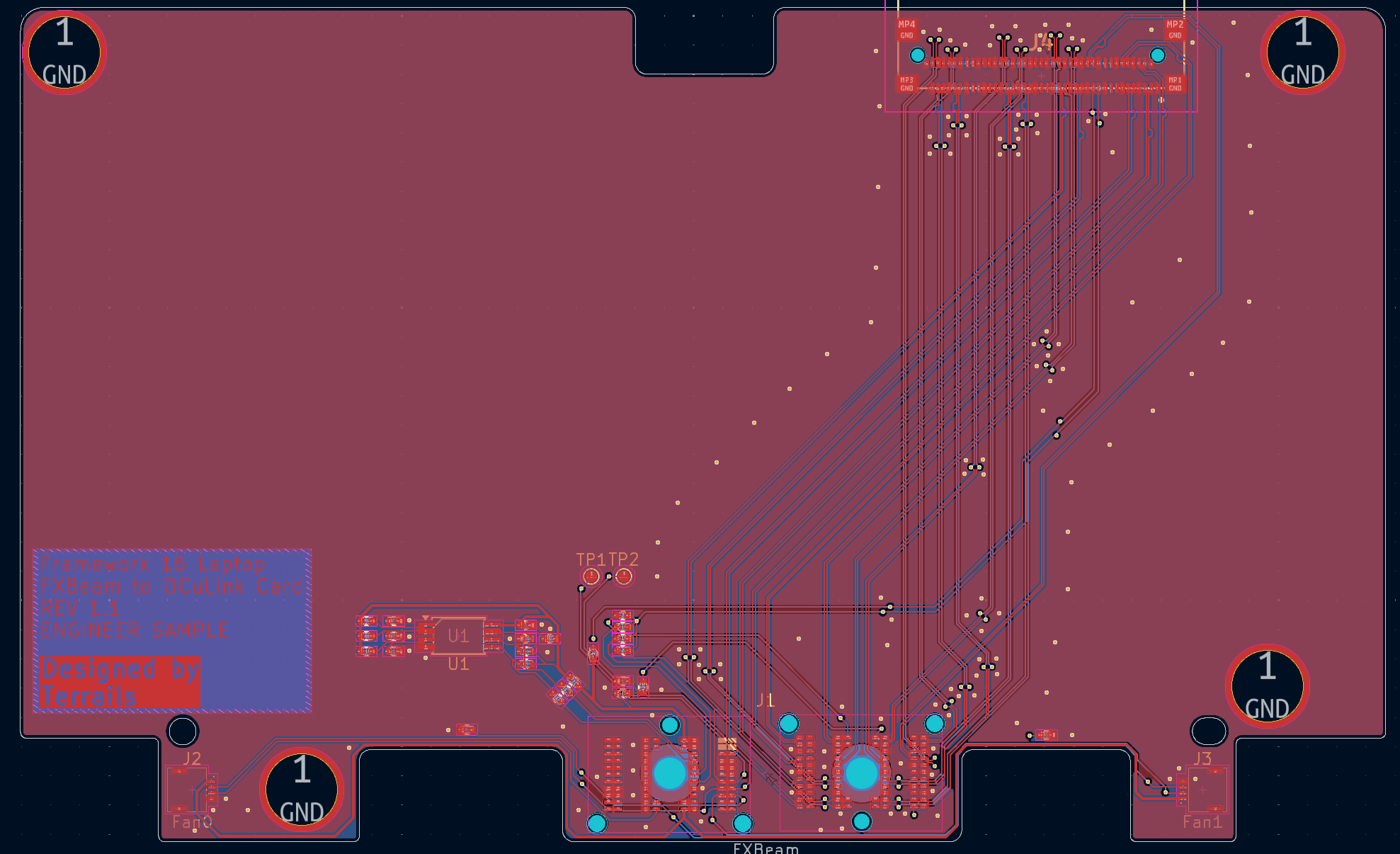
For the layout I have went with a 4-layer board and did manage to successfully stay within JLCPCB's fabrication limits. For the production runs I have done a 1.2mm ENIG board and used the Nan Ya NP-140F material type with the JLC04121H-1080 stackup and matched the differential pairs to it. I did also manage to stay within the minimum 0.3mm via hole size to keep costs somewhat down.
| Qty | Value | Footprint | References |
|---|---|---|---|
| 16 | 0R | Resistor_SMD:R_0402_1005Metric | R3, R4, R5, R7, R8, R10, R12, R13, R14, R15, R22, R23, R30, R33, R34, R36 |
| 6 | 1K | Resistor_SMD:R_0402_1005Metric | R16, R17, R19, R21, R28, R31 |
| 5 | 0.1U | Capacitor_SMD:C_0402_1005Metric | C1, C2, C3, C4, C5 |
| 5 | 100K | Resistor_SMD:R_0402_1005Metric | R11, R24, R25, R29, R32 |
| 4 | MountingHole_Pad | Expansion_Bay:MountingHole_6.2mm_EasySolder_Cut | H1, H2, H3, H4 |
| 2 | 10K | Resistor_SMD:R_0402_1005Metric | R18, R20 |
| 2 | 330K | Resistor_SMD:R_0402_1005Metric | R1, R2 |
| 2 | 4.7K | Resistor_SMD:R_0402_1005Metric | R6, R9 |
| 2 | 47K | Resistor_SMD:R_0402_1005Metric | R26, R27 |
| 2 | Fan | FPC_Conn:AFC58-S04FIA_4Pin | J1, J2 |
| 2 | TL331LV | Package_TO_SOT_SMD:SOT-23-5 | U2, U3 |
| 1 | BR24G32FVT-3GE2 | Package_SO:TSSOP-8_4.4x3mm_P0.65mm | U1 |
| 1 | FXBeam | Expansion_Bay:FXBeam | J3 |
| 1 | I2C | Connector_JST:JST_SH_SM04B-SRSS-TB_1x04-1MP_P1.00mm_Horizontal | J4 |
| 1 | SW_DIP_x02 | Button_Switch_SMD:SW_DIP_SPSTx02_Slide_Copal_CHS-02B_W7.62mm_P1.27mm | SW2 |
| 1 | SW_DPDT_x2 | Switches:SSSS820101 | SW1 |
| 1 | USB_A | USB:87583-2010BLF | J5 |
| 1 | x8 NPIO | Nano_Pitch:Nano-Pitch-173162-0132 | J6 |
Popax21/framework16-cellular
A M.2 cellular modem Expansion Bay module for the Framework Laptop 16

Fr4nkFletcher/ESP32-Marauder-Cheap-Yellow-Display
ESP32Marauder Cheap Yellow Display


opentac/opentac
OpenTac: open tools to design, fabricate, read and simulate flex-PCB tactile skins that sense normal and shear force, for any robot surface.

AlexeyInwerp/BoardRipper
Web-based PCB boardview viewer for board-level repair. 14 formats: BVR1/3, BRD, BDV, BDV ASC, FZ, GenCAD, Mentor Neutral, XZZ, TVW, Allegro v15-v18, Altium, KiCad, EAGLE.


screwbreaker/ScartPCB
A little PCB to buld a SCART cable for console and old computers
It measures 119 × 73.9 mm and has 4 copper layers, 1.14 mm thick.
55 parts, built around the TL331LVDBV and BR24G32FVT-3GE2. The full list of its parts is on this page, with links to each part's symbol and footprint where PCBKit's library has them.
From the Terrails/FW16-OCuLink repository on GitHub, at the commit this page was made from: the board is fw16_oculink8i.kicad_pcb and its schematic fw16_oculink8i.kicad_sch. PCBKit opens the board in the browser, with nothing to install.
Its repository publishes it under the MIT licence: you may reuse it on that licence's terms (keep the author's notice, and for a copyleft licence share your changes alike).