2 layers49.8 × 24.3 mm
FSP Display5S
MobiFlight/mobiflight-panels
A repository with open source panel designs for flight simulation.
13 parts126GPL-3.0

 TeknoTrek/Si5351-Clock-Generator-for-Arduino-Projects4
Si5351 Clock Generator for Arduino Projects Generate precise clock signals using the Si5351 module and Arduino Nano. Features: Stable clock outputs with Si5351. Rotary encoder for easy frequency adjustment. Compact, DIY-friendly PCB design. Watch on YouTube: https://youtu.be/GfB7mTY67xE
Si5351-Signal Generator is an open-source printed circuit board by TeknoTrek, from the TeknoTrek/Si5351-Clock-Generator-for-Arduino-Projects repository on GitHub. It is a 2-layer board of 90 × 70 mm with 16 parts on 35 nets, routed with 103 tracks and 0 vias.
It is built around the JUMPER2. Its parts include 5 capacitors, 2 ICs, 2 connectors, 2 switches and 1 resistor. It belongs with the lEDs and displays boards and the AVR (ATmega, ATtiny) boards of this library.
This project showcases how to create a clock generator using the Si5351 module with an Arduino Nano. It includes an OLED display for visual feedback and supports frequency adjustments through an encoder. The project is designed for electronics enthusiasts and engineers looking to generate precise clock signals for various applications.

The schematic includes:
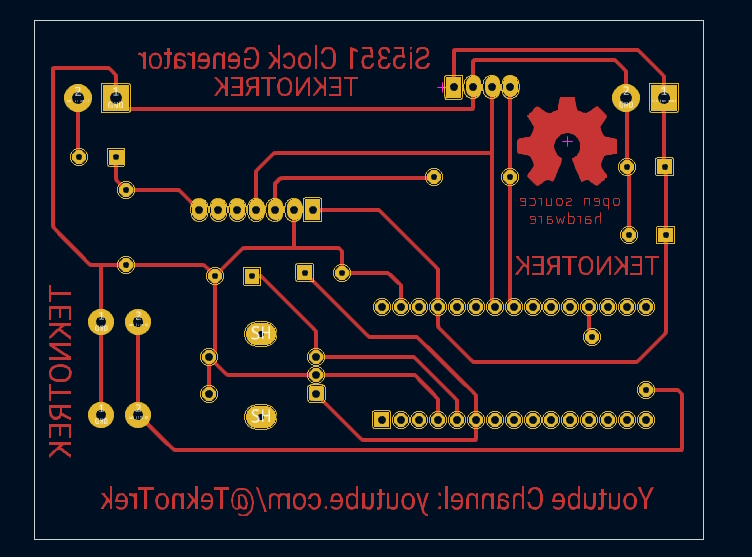
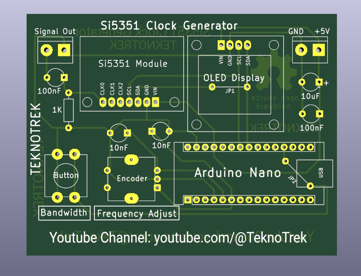
The PCB is designed to accommodate:
The Arduino sketch for this project initializes the Si5351 module and OLED display, processes encoder inputs, and outputs clock signals.
Code will be provided in the GitHub repository.
Check out the video demonstration of the project on our YouTube channel:
This project is licensed under the MIT License. Feel free to use, modify, and share it!
Feel free to open issues or submit pull requests to improve the project.
For any inquiries, reach out via:
| Qty | Value | Footprint | References |
|---|---|---|---|
| 2 | 100nF | Capacitor_THT:CP_Radial_Tantal_D5.0mm_P5.00mm | C4, C5 |
| 2 | 10nF | Capacitor_THT:CP_Radial_Tantal_D5.0mm_P5.00mm | C2, C3 |
| 2 | Jumper_2 | Resistor_THT:R_Axial_DIN0207_L6.3mm_D2.5mm_P10.16mm_Horizontal | JP1, JP2 |
| 1 | 10uF | Capacitor_THT:CP_Radial_Tantal_D5.0mm_P5.00mm | C1 |
| 1 | 1K | Resistor_THT:R_Axial_DIN0207_L6.3mm_D2.5mm_P10.16mm_Horizontal | R1 |
| 1 | Arduino_Nano_v3.x | Module:Arduino_Nano | A1 |
| 1 | DC +5V | TerminalBlock:TerminalBlock_bornier-2_P5.08mm | J2 |
| 1 | DECR | Button_Switch_THT:SW_PUSH-12mm | S1 |
| 1 | Encoder | Rotary_Encoder:RotaryEncoder_Bourns_Vertical_PEC12R-3x17F-Sxxxx | SW1 |
| 1 | OLED-Display-128x64 | My-Library:OLED-DISPLAY-128X64 | U1 |
| 1 | Si5351-Modul | My-Library:Si5351-Module | U2 |
| 1 | Singnal Out | TerminalBlock:TerminalBlock_bornier-2_P5.08mm | J1 |
The 15 most common of 16 parts.
MobiFlight/mobiflight-panels
A repository with open source panel designs for flight simulation.

myriadrf/reference-development-kit
The Myriad-RF Reference Hardware design files and firmware


TeknoTrek/LC-Meter
This repository is part of the Teknotrek YouTube channel, featuring the DIY LC Meter project. It includes KiCad files, schematics, PCB layouts, and Arduino firmware.

DCC-EX/EX-Hardware
Open Source hardware projects developed by the DCC-EX Team

abdontroche/FabISP-USBtinyISP-ATtiny44
This is a version of the Fab-ISP programmer that is used in the Fab Academy course around the world

matthiasnowak/jewelled
This is a panel meant for production of the Earrings, allowing for 2 Earrings per panel.
It measures 90 × 70 mm and has 2 copper layers, 1.6 mm thick.
16 parts, built around the JUMPER2. The full list of its parts is on this page, with links to each part's symbol and footprint where PCBKit's library has them.
From the TeknoTrek/Si5351-Clock-Generator-for-Arduino-Projects repository on GitHub, at the commit this page was made from: the board is Si5351-Signal-Generator/si5351-Signal-Generator.kicad_pcb and its schematic Si5351-Signal-Generator/si5351-Signal-Generator.kicad_sch. PCBKit opens the board in the browser, with nothing to install.
Its repository states no licence, so its author keeps all rights: ask TeknoTrek before reusing the design.