
2 layers79.8 × 138.9 mm
CircuitBoard
Technologyman00/Teensy-PC_RGB_Controller
An Open Source RGB Controller with enough ports to light up the sky. No processing load on your computer either!
52 parts1GPL-3.0

 Technologyman00/Teensy-PC_RGB_Controller1
An Open Source RGB Controller with enough ports to light up the sky. No processing load on your computer either!
CircuitBoardV2 is an open-source printed circuit board by Technologyman00, from the Technologyman00/Teensy-PC_RGB_Controller repository on GitHub, published under the GPL-3.0 licence. It is a 2-layer board of 57.4 × 132.3 mm with 53 parts on 131 nets, routed with 723 tracks and 31 vias.
It is built around the TXS0108EPWR. Its parts include 42 connectors and 5 ICs. It belongs with the lEDs and displays boards of this library.
The whole Idea behind this project was to create a much better RGB controller than the controllers or motherboard software I have seen. Currently It has already met that goal as it can play any pattern for many LEDs and up to individual 40 devices. I am still working on the user interface and many qualities of life things, but the main functionality does work. HOWEVER, it will need a PCB made to power all the LEDs as a Teensy cannot power that many safely.
| Description | Command | Argument 1 | Argument 2 |
|---|---|---|---|
| Send RGB Command: | 0 | Port Number | Color Data |
| Send HSV Command: | 1 | Port Number | Hue (2 Bytes) S (1 Byte) V (1 Byte) |
| Change Frame Delay: | 2 | Delay (2 Bytes) | N/A |
| Create Device/Change Length: | 3 | Port Number | Number of Pixels |
| Start New Frame: | 4 | N/A | N/A |
Port 13 is not accessable from the hardware as it has the status LED so it was intentionally skipped in the PCB design.
Color Data is a continuous set of the RGB or HSV values. It will be (3 * Number of Pixels in Device) bytes long. For example it would go (Red Byte)(Blue Byte)(Green Byte)(Red Byte)(Blue Byte)(Green Byte)... or (Hue Byte)(Saturation Byte)(Value Byte)(Hue Byte)(Saturation Byte)(Value Byte)... All these bytes are from 0-255 with no decimals, as bytes are. For hue, saturation, and value these are all scaled to their corrective values.
The delay value is split into 2 different bytes to allow a delay between 0 and 65535ms or 65.5 seconds. This allows a great range between quick animations and still colors. This value does not matter so much for still colors as the pattern file will just start over once it reaches the end re-displaying the same color.
| Description | Command | Argument 1 | Argument 2 | Argument 3 |
|---|---|---|---|---|
| Play File on SD Card: | P | File Name | N/A | N/A |
| Write File to SD Card: | W | File Name | Length to Read (4 Bytes) | File Data |
| Delete File on SD Card: | X | File Name | N/A | N/A |
| List Files on SD Card: | L | N/A | N/A | N/A |
| Change Startup File: | S | File Name | N/A | N/A |
| Display Frame: | D | RGB or HSV -> (0 or 1) | Port Number | Color Data |
| New Device: | N | Port | Number of Pixels | N/A |
| Restart Teensy: | R | N/A | N/A | N/A |
| Check Teensy Tempature: | T | N/A | N/A | N/A |
On startup the teensy will first read the startup.txt file which should contain the name of the file and only the name of the file. If this file does not exist or the code is unhappy with what was entered it will delete the startup.txt file and replace it with a startup.txt file that will run the default pattern file. The default pattern file sets all 40 ports to display Green on 255 pixels on those ports. This should make it so that it is obvious that the Teensy is working. The startup.txt file can be changed by either editing the file in a text editor or by sending the S command over serial.
6/6 Full Deployment!!!!! Example 1: https://youtu.be/utrNA2Hu2Kg Example 2: https://youtu.be/6SqUPKUgLiA
5/30 Version 2 of the PCB was ordered and should be arriving shortly. This new version is to fix the concerns with the previous version, as the size was quite large and there was a design error. Both should be fixed in this version. Pin 13 was also taken off of the available pins as it was decided that it should be used as a status LED and should remain off if used.
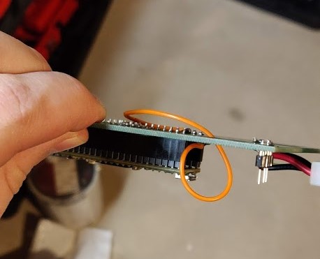
3/14 PCB Came in had issues. The Output enable pin was grounded not powered, which means it was disabled not enabled. (Woops) A small soldered wire fixed that. First Test : https://youtu.be/IeGvDfm8C_M
| Qty | Value | Footprint | References |
|---|---|---|---|
| 40 | Conn_01x04_Male | Connector:FanPinHeader_1x04_P2.54mm_Vertical | J1, J2, J10, J11, J12, J13, J14, J15, J16, J17, J18, J19, J20, J23, J24, J25 +24 |
| 5 | TXS0108EPWR | TXS0108EPWR:SOP65P640X120-20N | U1, U2, U3, U4, U5 |
| 2 | Conn_01x24_Female | Connector_PinSocket_2.54mm:PinSocket_1x24_P2.54mm_Vertical | J21, J22 |
| 1 | Conn_01x04_Male | Molex:7708461 | JMolex1 |
| 1 | LOGO | OpenSource:OpenSourceFix | G*** |
The 49 most common of 53 parts.
Technologyman00/Teensy-PC_RGB_Controller
An Open Source RGB Controller with enough ports to light up the sky. No processing load on your computer either!

BerkeleyLab/Marble
Dual FMC FPGA carrier board developed for general purpose use in particle accelerator electronics instrumentation.


BroncoSpace-Lab/scales-hardware
Hardware design files for the Spacecraft Compartmentalized Autonomous Learning and Edge Computing System (SCALES)


rein-baremetal/REIN_R1_KiCad
Dual-MCU baremetal embedded development board featuring high-speed QSPI storage, hardware USB hub, and flexible power management. Open for PCB trace routing collaboration

BILLEE-BroncoSTAR/billee-hardware-2027
Hardware and firmware Repository for BILLEE URC 2027
It measures 57.4 × 132.3 mm and has 2 copper layers, 1.6 mm thick.
53 parts, built around the TXS0108EPWR. The full list of its parts is on this page, with links to each part's symbol and footprint where PCBKit's library has them.
From the Technologyman00/Teensy-PC_RGB_Controller repository on GitHub, at the commit this page was made from: the board is 2 PCB/V2 Board KiCad 5.99/CircuitBoardV2/CircuitBoardV2.kicad_pcb and its schematic 2 PCB/V2 Board KiCad 5.99/CircuitBoardV2/CircuitBoardV2.kicad_sch. PCBKit opens the board in the browser, with nothing to install.
Its repository publishes it under the GPL-3.0 licence: you may reuse it on that licence's terms (keep the author's notice, and for a copyleft licence share your changes alike).