Skip to the content
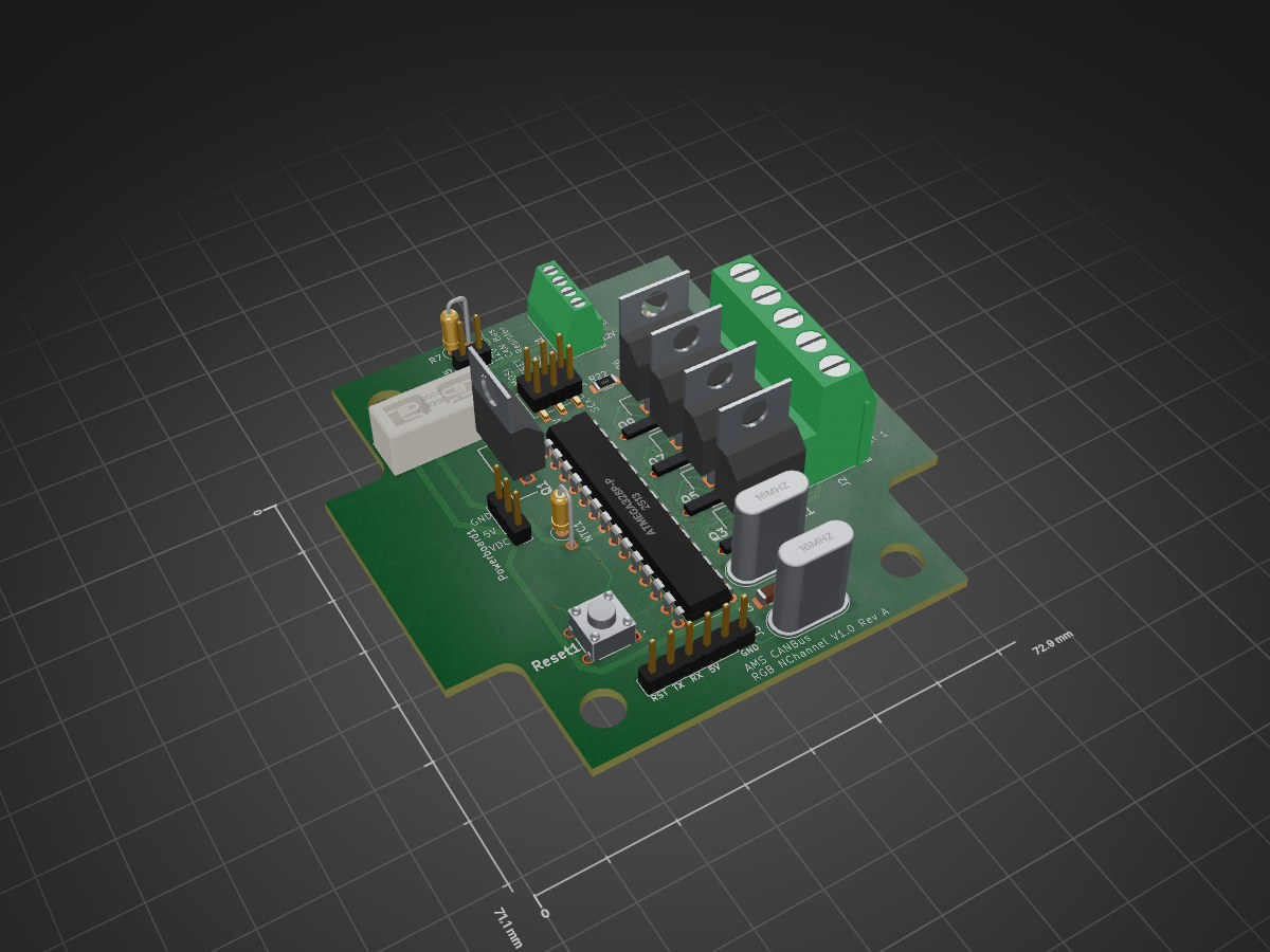
2 layers72.9 × 71.1 mmAMS - CANBus - RGB - Nchannel, the printed circuit board in 3D

What is this? --- when working on my AMS solution i kept putting more and more stuff into a single box and everytime i needed to make a change it was $200 for a board that may or may not work so i decided to make it…

Size
72.9 × 71.1 mm
Copper layers
2
Thickness
1.6 mm
Parts
59
Nets
64
Pads
195
Tracks, vias
513, 27
Routed
Yes
KiCad
KiCad 8.0 (file 20240108)
Created
6 Apr 2024
Updated
13 Aug 2026

Overview

AMS - CANBus - RGB - Nchannel is an open-source printed circuit board by TJLTM, from the TJLTM/Automotive-Monitoring-System-CANBus-Sensor repository on GitHub. It is a 2-layer board of 72.9 × 71.1 mm with 59 parts on 64 nets, routed with 513 tracks and 27 vias.

It is built around the ATMEGA328P-PU, MCP2551-I/SN-HG and IRF9Z34NPBF, with the BZX79C10, PESD5V0L2UU,115-ES and TS02-66-160-BK-260-LCR-D among its other parts. Its parts include 21 resistors, 10 transistors, 8 capacitors, 5 connectors and 4 ICs. It belongs with the interfaces and adapters and lEDs and displays boards and the AVR (ATmega, ATtiny) boards of this library.

Main components

6

README

README.md

What is this? --- when working on my AMS solution i kept putting more and more stuff into a single box and everytime i needed to make a change it was $200 for a board that may or may not work so i decided to make it easier on myself to split the sensors up so that it isn't a bespoke solution for a single car application.

these are the sensor hardware designs that match up with https://github.com/TJLTM/Automotive-Monitoring-System-CANBus-Sensor-FW repo so that i can keep the Hardware designs over here and the FW over there. mostly just so i'm not in some weird state where i'm working on a FW for one thing and the hardware for another and get into a screwed up merge situation. this has happened before in my other projects.

If you look at the other repo you'll see i've made provisions for the following sensors

  • Temp (RTD)
  • Voltage (ADC)
    • Pressure
    • Current
    • Temp (not RTD Based)
    • Any sensor that outputs a votlage signal if gain is needed that would have to be added
  • Vacuum
  • I/O
  • RPM
  • LED or other general Output
    • P-channel
    • N-channel

The other boards ahve the hardware built on to the boards since those require some type of special sensor

Vacuum sensor This one is something that i've been working on for a while since there aren't many direct vacuum sensors out there and it took me a while to figure out this design as most vacuum sensors or MAPs so a bit of math to do it. They take the Barometric pressure and then making a few assumptions use the differential to standard atmospherical pressure to give you the vacuum. The design i am using is a direct measurement of the vacuum via the honeywell sensor. Yes it's expensive to build. In fact it costs more to make one of those then all the others combined.

RPM sensor this one is a straight foreward design and i may make it an add on module for the ADC since really it's just a Freq to Voltage Sensor

The I/O box... That one i'm making it a standard 8 in and 8 out setup. can be made to i don't know.... hook into power window units in older cars that can then be remotely controlled or in my case add power windows to some cars.

LED General 3 Channel RGB leds can be driven off of this I'm making it 4 channel since i have the space for it. It can either be high or low side switching depending on your application. this is using the 0-255 PWM output of the AVR

I'm using my other design for power https://github.com/TJLTM/LM2670SX-Carrier but if you don't like it. BYOPS
Parts

59
QtyValueFootprintReferences
810kResistor_SMD:R_1206_3216Metric_Pad1.30x1.75mm_HandSolderR1, R3, R4, R5, R10, R13, R16, R19
51MResistor_SMD:R_1206_3216Metric_Pad1.30x1.75mm_HandSolderR8, R11, R14, R17, R20
52N7002Package_TO_SOT_SMD:SOT-23Q2, Q4, Q6, Q8, Q10
5IRF9Z34NPBFSamacSys_Parts:TO254P469X1042X1967-3PQ1, Q3, Q5, Q7, Q9
4100kResistor_SMD:R_1206_3216Metric_Pad1.30x1.75mm_HandSolderR9, R12, R15, R18
422pfCapacitor_SMD:C_1206_3216Metric_Pad1.33x1.80mm_HandSolderC2, C3, C4, C5
4BZX79C10SamacSys_Parts:DIOAD1068W53L380D172Z1, Z2, Z3, Z4
3100nfCapacitor_SMD:C_1206_3216Metric_Pad1.33x1.80mm_HandSolderC1, C6, C7
216MHzCrystal:Crystal_HC49-U_VerticalY1, Y2
110kResistor_THT:R_Axial_DIN0207_L6.3mm_D2.5mm_P2.54mm_VerticalNTC1
1120Resistor_THT:R_Axial_DIN0207_L6.3mm_D2.5mm_P2.54mm_VerticalR7
117kResistor_THT:R_Axial_DIN0207_L6.3mm_D2.5mm_P2.54mm_VerticalR6
11N4007Diode_THT:D_DO-41_SOD81_P10.16mm_HorizontalD2
122kResistor_SMD:R_1206_3216Metric_Pad1.30x1.75mm_HandSolderR22
122nFResistor_SMD:R_1206_3216Metric_Pad1.30x1.75mm_HandSolderC8
13568SamacSys_Parts:3568U5
14.7kResistor_SMD:R_1206_3216Metric_Pad1.30x1.75mm_HandSolderR2
1ATmega328P-PPackage_DIP:DIP-28_W7.62mmU2
1Conn_01x02Connector_PinHeader_2.54mm:PinHeader_1x02_P2.54mm_VerticalJ5
1Conn_01x03Connector_PinHeader_2.54mm:PinHeader_1x03_P2.54mm_VerticalPowerboard1
1ICSPConnector_PinHeader_2.54mm:PinHeader_2x03_P2.54mm_Vertical_SMDJ4
1MCP2515-xSOPackage_SO:SOIC-18W_7.5x11.6mm_P1.27mmU3
1MCP2551-I-SNPackage_SO:SOIC-8_3.9x4.9mm_P1.27mmU4
1PESD5V0L2UU,115SamacSys_Parts:SOT65P210X110-3ND1
1Power_And_CANTerminalBlock_Phoenix:TerminalBlock_Phoenix_MPT-0,5-4-2.54_1x04_P2.54mm_HorizontalJ1
1Screw_Terminal_01x05TerminalBlock_Phoenix:TerminalBlock_Phoenix_MKDS-3-5-5.08_1x05_P5.08mm_HorizontalJ2
1TS02-66-160-BK-260-LCR-DSamacSys_Parts:TS0266160BK260LCRDReset1
1TTL_ProgrammerConnector_PinHeader_2.54mm:PinHeader_1x06_P2.54mm_VerticalJ3

More from TJLTM/Automotive-Monitoring-System-CANBus-Sensor

8
  • 2 layers72.9 × 71.1 mmAMS - CANBus Sensor - Temperature - RTD, the printed circuit board in 3D

    AMS - CANBus Sensor - Temperature - RTD

    TJLTM/Automotive-Monitoring-System-CANBus-Sensor

    What is this? --- when working on my AMS solution i kept putting more and more stuff into a single box and everytime i needed to make a change it was $200 for a board that may or may not work so i decided to make it…

    59 parts
  • 2 layers72.9 × 71.1 mmAMS - CANBus Sensor - RPM, the printed circuit board in 3D

    AMS - CANBus Sensor - RPM

    TJLTM/Automotive-Monitoring-System-CANBus-Sensor

    What is this? --- when working on my AMS solution i kept putting more and more stuff into a single box and everytime i needed to make a change it was $200 for a board that may or may not work so i decided to make it…

    52 parts
  • 2 layers72.9 × 71.1 mmAMS - CANBus Sensor - Vacuum, the printed circuit board in 3D

    AMS - CANBus Sensor - Vacuum

    TJLTM/Automotive-Monitoring-System-CANBus-Sensor

    What is this? --- when working on my AMS solution i kept putting more and more stuff into a single box and everytime i needed to make a change it was $200 for a board that may or may not work so i decided to make it…

    51 parts
  • 2 layers72.9 × 71.1 mmAMS - CANBus Sensor - Voltage, the printed circuit board in 3D

    AMS - CANBus Sensor - Voltage

    TJLTM/Automotive-Monitoring-System-CANBus-Sensor

    What is this? --- when working on my AMS solution i kept putting more and more stuff into a single box and everytime i needed to make a change it was $200 for a board that may or may not work so i decided to make it…

    44 parts
  • 2 layers72.9 × 71.1 mmAMS - CANBus Sensor - IO, the printed circuit board in 3D

    AMS - CANBus Sensor - IO

    TJLTM/Automotive-Monitoring-System-CANBus-Sensor

    What is this? --- when working on my AMS solution i kept putting more and more stuff into a single box and everytime i needed to make a change it was $200 for a board that may or may not work so i decided to make it…

    34 parts
  • 4 layers50.4 × 49.6 mmAutomotive Monitoring System CANBus Sensor SMD Processor, the printed circuit board in 3D

    Automotive Monitoring System CANBus Sensor SMD Processor

    TJLTM/Automotive-Monitoring-System-CANBus-Sensor

    What is this? --- when working on my AMS solution i kept putting more and more stuff into a single box and everytime i needed to make a change it was $200 for a board that may or may not work so i decided to make it…

    30 parts
  • 4 layers50.4 × 49.6 mmAutomotive Monitoring System CANBus Sensor, the printed circuit board in 3D

    Automotive Monitoring System CANBus Sensor

    TJLTM/Automotive-Monitoring-System-CANBus-Sensor

    What is this? --- when working on my AMS solution i kept putting more and more stuff into a single box and everytime i needed to make a change it was $200 for a board that may or may not work so i decided to make it…

    30 parts
  • 2 layers72.9 × 71.1 mmAMS - CANBus Sensor - Voltage - 2 Out Daughter board, the printed circuit board in 3D

    AMS - CANBus Sensor - Voltage - 2 Out Daughter board

    TJLTM/Automotive-Monitoring-System-CANBus-Sensor

    What is this? --- when working on my AMS solution i kept putting more and more stuff into a single box and everytime i needed to make a change it was $200 for a board that may or may not work so i decided to make it…

    15 parts

Similar boards

  • 4 layers151.1 × 71.1 mmMakeItRain, the printed circuit board in 3D

    MakeItRain

    TJLTM/MakeItRain

    DIY ESP-32 Based sprinkler Controller

    76 parts3
  • 4 layers193.7 × 142.2 mmCampKeen, the printed circuit board in 3D

    CampKeen

    TJLTM/CampKeen

    What this can monitor: 1. Holding Tanks - Grey/Sewage via galvanic sensors (posts in the tank) these are the ones i'm using (https://www.amazon.com/gp/product/B07YVK2V2K/ref=ppxyodtbsearchasintitle?ie=UTF8&psc=1 and…

    326 parts
  • 2 layers329.9 × 146.6 mmBabyHuey, the printed circuit board in 3D

    BabyHuey

    tristancollins/HiFi-BabyHuey

    An "Engineer's" Baby Huey EL34 PCB

    201 parts5
  • 2 layers130 × 75 mmQ17-SIGMA PSU, the printed circuit board in 3D

    Q17-SIGMA PSU

    stefaweb/audio-psu

    Some power supply PCBs I developed.

    84 parts10GPL-3.0
  • 2 layers100 × 100 mmMaster old, the printed circuit board in 3D

    Master old

    formicidae-tracker/hardware

    Hardware repository for the FORT system

    663 parts1
  • 2 layers110 × 124 mmVision arm, the printed circuit board in 3D

    Vision arm

    deanasmith/vision-arm

    should be any of the following: - calibrate: Calibrate the cameras with the charuco board - track: Start tracking with multiple cameras - mono: Start with a single camera (mostly for debugging)

    68 parts
  • 6 layers160 × 120 mmPic32main, the printed circuit board in 3D

    Pic32main

    JuanPoueriet/automatic-spork

    Máquina de ruleta física de casino. 6 PCBs: pic32main (cerebro), wheel (rueda de LEDs), displaysa/b/c (paneles de 7 segmentos en cascada) y buttons (botonera).

    256 parts

Questions

How big is the AMS - CANBus - RGB - Nchannel PCB?

It measures 72.9 × 71.1 mm and has 2 copper layers, 1.6 mm thick.

What parts does the AMS - CANBus - RGB - Nchannel use?

59 parts, built around the ATMEGA328P-PU, MCP2551-I/SN-HG, IRF9Z34NPBF and BZX79C10. The full list of its parts is on this page, with links to each part's symbol and footprint where PCBKit's library has them.

Where can I download the AMS - CANBus - RGB - Nchannel KiCad files?

From the TJLTM/Automotive-Monitoring-System-CANBus-Sensor repository on GitHub, at the commit this page was made from: the board is AMS - CANBus - RGB - Nchannel/AMS - CANBus - RGB - Nchannel.kicad_pcb and its schematic AMS - CANBus - RGB - Nchannel/AMS - CANBus - RGB - Nchannel.kicad_sch. PCBKit opens the board in the browser, with nothing to install.

Can I use the AMS - CANBus - RGB - Nchannel design in my own project?

Its repository states no licence, so its author keeps all rights: ask TJLTM before reusing the design.