


2 layers41.4 × 47.5 mm
U2f zero panel
conorpp/u2f-zero
U2F USB token optimized for physical security, affordability, and style
52 parts2.4k

 SukkoPera/OpenAmigaVideoHybrid69
Open Hardware implementation of the Commodore Amiga Video Hybrid
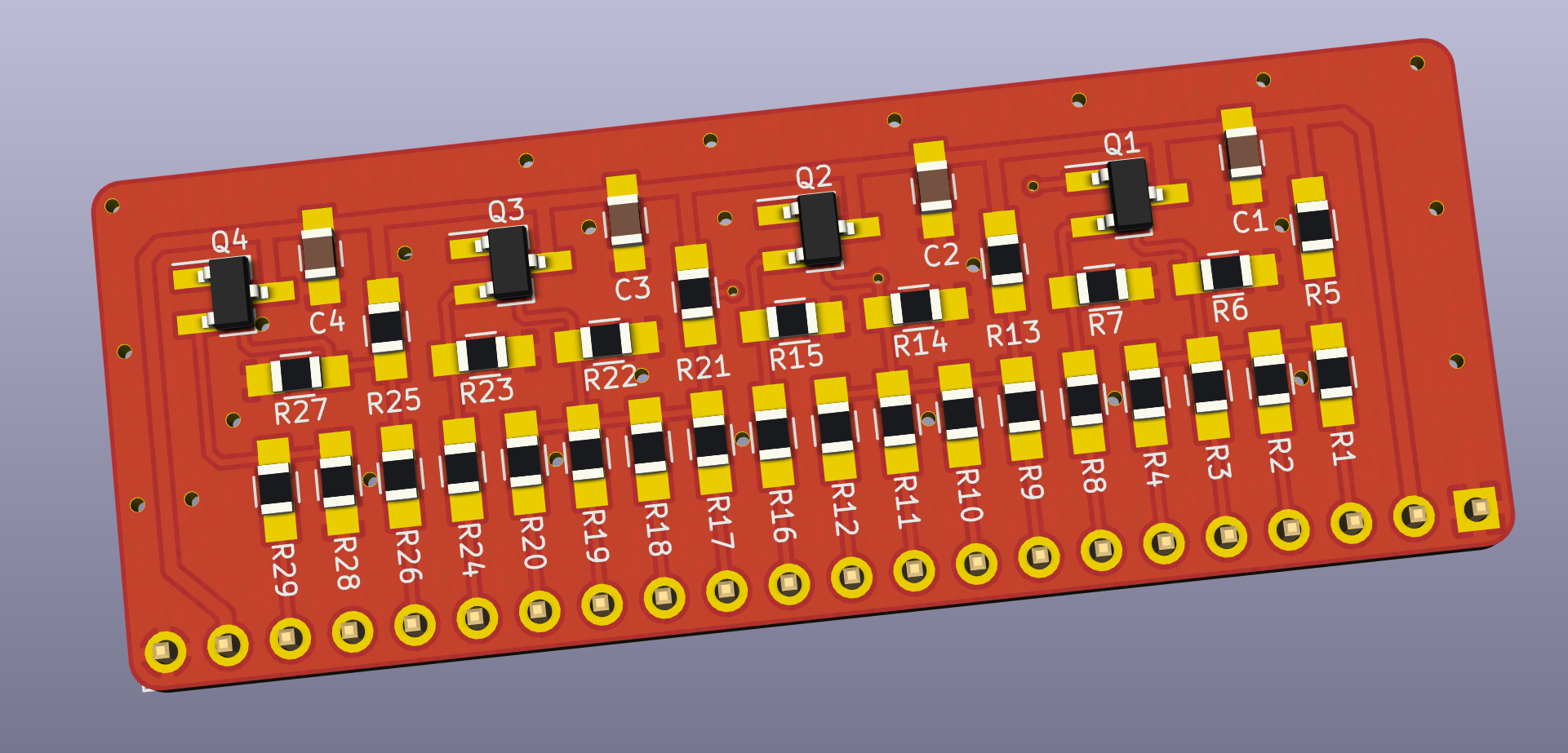
OpenAmigaVideoHybrid is an open-source printed circuit board by SukkoPera, from the SukkoPera/OpenAmigaVideoHybrid repository on GitHub. It is a 2-layer board of 56.4 × 21.1 mm with 52 parts on 32 nets, routed with 273 tracks and 29 vias.
Its parts include 39 resistors, 6 transistors, 5 capacitors and 2 connectors. It belongs with the retro computing and games boards of this library.
OpenAmigaVideoHybrid is an Open Hardware implementation of the Video Hybrid integrated circuit used in some Commodore Amiga computers (Commodore Part No. 390229-0x).
The Video Hybrid, also known as VIDIOT, is a hybrid integrated circuit acting as a Digital-to-Analog Converter (DAC), which converts the digital 4-bit per color video signal of the Amiga into standard (analog) signals suitable to drive a monitor or TV.
It is used in Amiga models A500, A500+, A1000, A2000 and A3000. The Amiga 3000 actually uses two Hybrids: one for the 15kHz video output from Denise and one for the 31kHz video output from Amber. Two Hybrids are also used in the GBA1000 A1000 Clone.
It is also used in some add-on cards, such as the Commodore A2320 Deinterlacer.
The Video Hybrid is a reliable component that usually "just works", but if it gets damaged there is no way of repairing it, the only option is to replace it.
The Video Hybrid has 5 sections, one for each of the red, green and blue colors, one for the synchronization signal and one for a composite monochrome signal.
The red, green and blue sections are identical: first, the digital signals are mixed together using the typical binary-weighted resistors DAC configuration. After that, the level of the resulting signal is amplified through an NPN transistor. At the output, the signal is terminated at 75 ohms, as is typical for video signals.
The composite signal is generated in a similar way. The only significant differences are that the weighting resistors have different values and that the amplifier has two stages (NPN + PNP), in order to achieve a higher gain.
The synchronization signal is digital by nature, thus it needs no conversion, only some amplification.
It should now be clear that the Video Hybrid is not much more than a bunch of resistors and transistors, plus a few capacitors.
The original Video Hybrid uses a lot of resistance values which are rather odd by today's standards. While resistors with said values can still be found, they are becoming increasingly rarer and rather expensive.
Besides that, while the basic circuit has always remained the same, Commodore has used different values for some resistors in different revisions of the Video Hybrid. In particular, revision 3 uses higher resistance values in the synchronization signal section. Presumably, this was done to suppress crosstalk among the RGB channels (especially at 31kHz).
What this all means is that newer designs should use different values that are cheap and easy to find, while maintaining functionality and performance.
The tables below lists the component values originally used by Commodore, along with some alternative values readily available in the E24 series, which is common and cheap today. Another column shows the values I actually use.
| Resistors | 390229-01/02 | 390229-03 | E24 | Sukko's | Manufacturer Part Number (MPN) |
|---|---|---|---|---|---|
| R1, R9, R17, R25** | 1k | 1k | 1k | 1k | CRG0805F1K0 |
| R2, R10, R18 | 2k | 2k | 2k | 2k | RMC1/10K202FTP |
| R3*, R11*, R19* | 4k | 4k | 3.9k | 8.2k||8.2k | 4.02k = CRCW08054K02FKEA, 3.9k = CRG0805F3K9 |
| R4*, R12*, R20* | 8k | 8k | 8.2k | 8.2k | 8.06k = CRCW08058K06FKEA, 8.2k = CRG0805F8K2 |
| R5, R13, R21 | 470 | 470 | 470 | 470 | CRG0805F470R |
| R6, R14, R22 | 390 | 390 | 390 | 390 | CRG0805F390R |
| R7, R8, R15, R16, R23, R24, R29**, R39*** | 75 | 75 | 75 | 75 | ERJ6RED75R0V |
| R26** | 220 | 220 | 220 | 220 | CRG0805F220R |
| R27** | 27k | 27k | 27k | 22k | 27k = CRG0805F27K |
| R28** | 150 | 150 | 150 | 220 | 150 = CRG0805F150R |
| R30*** | 18k | 90.9k | 91k | 100k | |
| R31*** | 7.5k | 37.4k | 62k | 68k | 68k = CRG0805F68K |
| R32*** | 2.7k | 13.3k | 22k | 22k | 22k = RMC1/10K223FTP |
| R33*** | 1.2k | 6.04k | 10k | 22k||22k | |
| R34*** | 7.5k | 37.4k | 62k | 68k | |
| R35*** | 3.9k | 19.6k | 20k | 22k | |
| R36*** | 120 | 270 | 220 | 220 | |
| R37***, R38*** | 36 | 36 | 36 | 75||75 | |
| Different Parts Count | 17 | 17 | 16 | 10 |
| Other Components | Value/MPN |
|---|---|
| C1, C2, C3, C4**, C5*** | 100nF |
| Q1, Q2, Q3, Q4**, Q5*** | MMBT3904 |
| Q6*** | MMBT3906 |
Notes:
Currently, OpenAmigaVideoHybrid has only been tested on the A500. On this model, you can mount it in vertical as the original Video Hybrid by using 90-degree pin headers, but I recommend a different approach:
OpenAmigaVideoHybrid is Open Hardware. If you make any modifications to the board, please contribute them back.
OpenAmigaVideoHybrid is provided to you ‘as is’ and without any express or implied warranties whatsoever with respect to its functionality, operability or use, including, without limitation, any implied warranties of merchantability, fitness for a particular purpose or infringement. We expressly disclaim any liability whatsoever for any direct, indirect, consequential, incidental or special damages, including, without limitation, lost revenues, lost profits, losses resulting from business interruption or loss of data, regardless of the form of action or legal theory under which the liability may be asserted, even if advised of the possibility or likelihood of such damages.
If you want to get some boards manufactured, you can get them from PCBWay through this link:

You get my gratitude and cheap, professionally-made and good quality PCBs, I get some credit that will help with this and other projects. You won't even have to worry about the various PCB options, it's all pre-configured for you!
Also, if you still have to register, you can use this link to get some bonus initial credit (and yield me some more).
You can also buy me a coffee if you want:

| Qty | Value | Footprint | References |
|---|---|---|---|
| 8 | 75 | Resistors_SMD:R_0805_HandSoldering | R7, R8, R15, R16, R23, R24, R29, R39 |
| 5 | 100n | Capacitors_SMD:C_0805_HandSoldering | C1, C2, C3, C4, C5 |
| 5 | 2N3904 | OpenAmigaVideoHybrid:2N3904_2N3906_SOT-23 | Q1, Q2, Q3, Q4, Q5 |
| 4 | 1k | Resistors_SMD:R_0805_HandSoldering | R1, R9, R17, R25 |
| 3 | 2k | Resistors_SMD:R_0805_HandSoldering | R2, R10, R18 |
| 3 | 390 | Resistors_SMD:R_0805_HandSoldering | R6, R14, R22 |
| 3 | 470 | Resistors_SMD:R_0805_HandSoldering | R5, R13, R21 |
| 3 | 4k | Resistors_SMD:R_0805_HandSoldering | R3, R11, R19 |
| 3 | 8k | Resistors_SMD:R_0805_HandSoldering | R4, R12, R20 |
| 2 | 220 | Resistors_SMD:R_0805_HandSoldering | R26, R36 |
| 2 | 36 | Resistors_SMD:R_0805_HandSoldering | R37, R38 |
| 2 | 37.4k | Resistors_SMD:R_0805_HandSoldering | R31, R34 |
| 1 | 13.3k | Resistors_SMD:R_0805_HandSoldering | R32 |
| 1 | 150 | Resistors_SMD:R_0805_HandSoldering | R28 |
| 1 | 19.6k | Resistors_SMD:R_0805_HandSoldering | R35 |
| 1 | 27k | Resistors_SMD:R_0805_HandSoldering | R27 |
| 1 | 2N3906 | OpenAmigaVideoHybrid:2N3904_2N3906_SOT-23 | Q6 |
| 1 | 6.04k | Resistors_SMD:R_0805_HandSoldering | R33 |
| 1 | 90.9k | Resistors_SMD:R_0805_HandSoldering | R30 |
| 1 | Conn_01x22 | OpenAmigaVideoHybrid:Pin_Header_Straight_1x22_Pitch2.54mm | J1 |
| 1 | OSHW_LOGO | w_logo:Logo_copper_OSHW_6x6mm | J99 |
conorpp/u2f-zero
U2F USB token optimized for physical security, affordability, and style

sudomesh/disaster-radio
A (paused) work-in-progress long-range, low-bandwidth wireless disaster recovery mesh network powered by the sun.

Neumi/open_echo
Open Source echo sounder / depth sounder / SONAR for bathymetry and research. Arduino based and compatible.

karawin/Ka-Radio
A wifi webradio with only low cost boards ESP8266 and VS1053 by Jp Cocatrix


StuckAtPrototype/AirCube
Works standalone out of the box. Pairs with Home Assistant in minutes. Other platforms are supported through community-contributed extensions.

Ardumower/ardumower
Develop an open source robotic lawn mower (HW+SW reference platform)

loxodes/vna
Under development open hardware microwave vector network analyzer
It measures 56.4 × 21.1 mm and has 2 copper layers, 1.6 mm thick.
52 parts. The full list of its parts is on this page, with links to each part's symbol and footprint where PCBKit's library has them.
From the SukkoPera/OpenAmigaVideoHybrid repository on GitHub, at the commit this page was made from: the board is OpenAmigaVideoHybrid.kicad_pcb. PCBKit opens the board in the browser, with nothing to install.
Its repository states no licence, so its author keeps all rights: ask SukkoPera before reusing the design.