
2 layers132.1 × 213.4 mm
 SukkoPera/DatassetteAudioAdapter13
Replace the Commodore Datassette with any audio source!
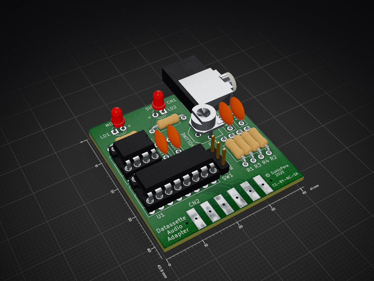
DatassetteAudioAdapter is an open-source printed circuit board by SukkoPera, from the SukkoPera/DatassetteAudioAdapter repository on GitHub. It is a 2-layer board of 41 × 43.6 mm with 20 parts on 26 nets, routed with 116 tracks and 12 vias.
It is built around the CD4049BD. Its parts include 6 resistors, 4 capacitors, 3 connectors, 2 ICs and 1 switch. It belongs with the retro computing and games and audio and music boards of this library.
DatassetteAudioAdapter is a simple adapter that allows connecting any audio source to the Datassette port of a Commodore VIC-20, 64, 128 or Plus/4 computer.

With this adapter, any audio source can be used in place of the proprietary Commodore Datassette, in order to load software into a Commodore computer through the dedicated port.
This project is similar to MP32C64 but it is implemented in a slightly different way, with a real opamp for the initial signal amplification.
It seems to have been originally developed by ZX_Jim, probably inspired by a similar adapter for the ZX Spectrum, which he might have actually developed himself.
In my experience this adapter works just as well as the other one: beside Audio CDs, MP3 files will also work, so a smartphone (provided that you have an old model with an audio jack...) or any other audio player can be used.
PRG files can be converted to audio using the WAV-PRG software suite.
The adapter can either be built with a PJRAN1X1U01X RCA/Cinch connector or with a SJ1-3525N 3.5" headphone jack connector, according to your preference. Note that the RCA connector will point towards the back, while the headphone jack will point to the right.
Usage should be straightforward. The only thing to be careful with is the playback volume: start with 0 and gradually increase it until the Signal LED is constantly on. You can still go up a few ticks from there, experiment a bit until you have successful loads.
If the audio player you are using has a volume knob, set the onboard volume control to the maximum and do the above with the knob on the player.
If you want to get this board produced, you are recommended to get the latest release rather than the current git version, as the latter might be under development and is not guaranteed to be working.
Every release is accompanied by its Bill Of Materials (BOM) file and any relevant notes about it, which you are recommended to read carefully.
The DatassetteAudioAdapter documentation, including the design itself, is copyright © SukkoPera 2025 and is licensed under the Creative Commons Attribution-NonCommercial-ShareAlike 4.0 International License.
This documentation is distributed as is and WITHOUT ANY EXPRESS OR IMPLIED WARRANTIES whatsoever with respect to its functionality, operability or use, including, without limitation, any implied warranties OF MERCHANTABILITY, SATISFACTORY QUALITY, FITNESS FOR A PARTICULAR PURPOSE or infringement. We expressly disclaim any liability whatsoever for any direct, indirect, consequential, incidental or special damages, including, without limitation, lost revenues, lost profits, losses resulting from business interruption or loss of data, regardless of the form of action or legal theory under which the liability may be asserted, even if advised of the possibility or likelihood of such damages.
If you want to get some boards manufactured, you can get them from PCBWay through this link:

You get my gratitude and cheap, professionally-made and good quality PCBs, I get some credit that will help with this and other projects. You won't even have to worry about the various PCB options, it's all pre-configured for you!
Also, if you still have to register, you can use this link to get some bonus initial credit (and yield me some more).
You can also buy me a coffee if you want:

| Qty | Value | Footprint | References |
|---|---|---|---|
| 4 | 1k | Resistor_THT:R_Axial_DIN0207_L6.3mm_D2.5mm_P10.16mm_Horizontal | R1, R4, R5, R6 |
| 2 | 100k | Resistor_THT:R_Axial_DIN0207_L6.3mm_D2.5mm_P10.16mm_Horizontal | R2, R3 |
| 2 | 100n | Capacitor_THT:C_Disc_D7.0mm_W2.5mm_P5.00mm | C3, C4 |
| 2 | LED | LED_THT:LED_D3.0mm | LD1, LD2 |
| 1 | 10k | DatassetteAudioAdapter:Pot_Bourns_3306P | RV1 |
| 1 | 1n | Capacitor_THT:C_Disc_D7.0mm_W2.5mm_P5.00mm | C2 |
| 1 | 47n | Capacitor_THT:C_Disc_D7.0mm_W2.5mm_P5.00mm | C1 |
| 1 | AUDIO_IN | DatassetteAudioAdapter:SWITCHCRAFT_PJRAN1X1U01X | CN1 |
| 1 | AUDIO_IN_JACK | DatassetteAudioAdapter:AudioJack_SJ1-3525N | CN101 |
| 1 | CD4049 | Package_DIP:DIP-16_W7.62mm_Socket_LongPads | U1 |
| 1 | LM741 | Package_DIP:DIP-8_W7.62mm_Socket_LongPads | U2 |
| 1 | OSHW_LOGO | DatassetteAudioAdapter:cc_by_nc_sa_small | V0 |
| 1 | SW_INVERT1 | Connector_PinHeader_2.54mm:PinHeader_1x03_P2.54mm_Vertical | SW1 |
| 1 | TAPE_PORT | DatassetteAudioAdapter:C64-Cassette-Port-Female | CN2 |

Desval27/FormantKO
Knock-off of the Elektor Formant Synthesizer project with the initial goal of being quasi-authentic and secondary goal undecided. Probably tweaks of some kind.


atopile/atopile
Design circuit boards with code! ✨ Get software-like design reuse 🚀, validation, version control and collaboration in hardware; starting with electronics ⚡️

davidphilipbarr/Sweep
Sweep - a small promicro based keyboard inspired by the Ferris.

rusefi/rusefi
rusefi - GPL internal combustion engine control unit

hoglet67/RGBtoHDMI
Bare-metal Raspberry Pi project that provides pixel-perfect sampling of Retro Computer RGB/YUV video and conversion to HDMI
It measures 41 × 43.6 mm and has 2 copper layers, 1.6 mm thick.
20 parts, built around the CD4049BD. The full list of its parts is on this page, with links to each part's symbol and footprint where PCBKit's library has them.
From the SukkoPera/DatassetteAudioAdapter repository on GitHub, at the commit this page was made from: the board is DatassetteAudioAdapter.kicad_pcb. PCBKit opens the board in the browser, with nothing to install.
Its repository states no licence, so its author keeps all rights: ask SukkoPera before reusing the design.