


2 layers70 × 50 mm
Fuel capacity sensor
gpgreen/fuel_capacity_sensor
KiCAD hardware design for Fuel Tank Capacity Sensor for capacitance style RV tank with CAN output
87 parts
This repository contains the code and hardware design used in my thesis on Steady-State Visually Evoked Potential (SSVEP) Brain-Computer Interfaces. It includes signal acquisition, processing, and classification methods, along with the corresponding circuit implementation.
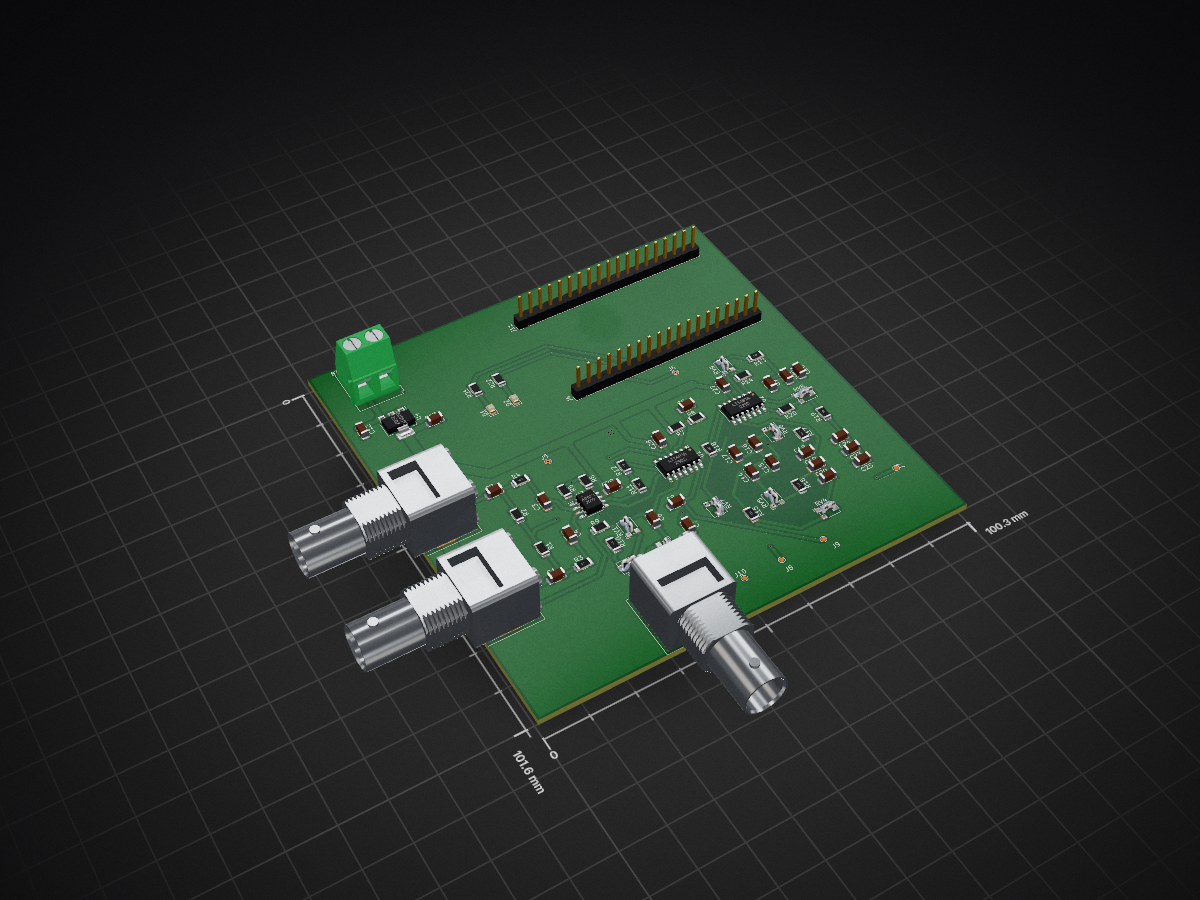
Eeg pcb v4 is an open-source printed circuit board by Spiros7bit, from the Spiros7bit/SSVEP-Based-Brain-Computer-Interface-BCI repository on GitHub. It is a 2-layer board of 100.3 × 101.6 mm with 75 parts on 80 nets, routed with 315 tracks and 38 vias.
It is built around the LT1491AIN and AMS1117. Its parts include 26 capacitors, 22 resistors, 11 connectors, 4 ICs and 2 diodes. It belongs with the interfaces and adapters boards of this library.
This project implements a real-time Steady-State Visually Evoked Potential (SSVEP) Brain-Computer Interface (BCI) using an ESP32 microcontroller and a custom PCB for analog interface. It was developed as part of a thesis and demonstrates how EEG signals can be processed and classified in real time on embedded hardware.
The system detects brain responses to visual stimuli at specific frequencies and converts them into control decisions.
The signal processing pipeline consists of the following stages:
Analog Interface
Signal Acquisition
Preprocessing
Feature Extraction
Decision Making
Output
ADC Input: GPIO34 (ADC1_CHANNEL_6)
A hardware timer triggers ADC sampling at 1000 Hz. Each sample is processed in real time.
A simple IIR filter removes the DC component from the signal:
dc_est = dc_est + k * (x - dc_est)A band-pass FIR filter is applied to isolate relevant EEG frequencies.
The Goertzel algorithm is used to compute the energy at specific target frequencies efficiently.
Two decision methods are implemented:
Argmax
MAD (Median Absolute Deviation)
The system outputs data via Serial in the following format:
signal_value, argmax_decision, mad_decisionThis can be visualized using the Arduino Serial Plotter.
.
├── main.ino
├── fir_new_2_1000hz.h   # FIR filter coefficients
├── README.mdDeveloped as part of a thesis project on SSVEP-based Brain-Computer Interfaces.
| Qty | Value | Footprint | References |
|---|---|---|---|
| 20 | C | Capacitor_SMD:C_1206_3216Metric | C10, C11, C12, C13, C14, C15, C16, C17, C18, C19, C20, C23, C24, C25, C27, C28 +4 |
| 9 | R | Resistor_SMD:R_1206_3216Metric | R5, R6, R7, R8, R9, R14, R20, R21, R22 |
| 6 | Conn_01x01_Pin | TestPoint:TestPoint_Pad_D1.0mm | J5, J6, J7, J8, J9, J10 |
| 4 | R_Potentiometer | Potentiometer_SMD:Potentiometer_Bourns_TC33X_Vertical | RV3, RV7, RV8, RV9 |
| 3 | 1k | Resistor_SMD:R_1206_3216Metric | R11, R12, R18 |
| 3 | Conn_Coaxial | Connector_Coaxial:BNC_Amphenol_B6252HB-NPP3G-50_Horizontal | J1, J2, J3 |
| 2 | 10k | Resistor_SMD:R_1206_3216Metric | R13, R19 |
| 2 | 10n | Capacitor_SMD:C_1206_3216Metric | C3, C4 |
| 2 | 1meg | Resistor_SMD:R_1206_3216Metric | R1, R2 |
| 2 | 2u | Capacitor_SMD:C_1206_3216Metric | C1, C2 |
| 2 | 30k | Resistor_SMD:R_1206_3216Metric | R16, R17 |
| 2 | 3k | Potentiometer_SMD:Potentiometer_Bourns_TC33X_Vertical | RV5, RV6 |
| 2 | 500k | Potentiometer_SMD:Potentiometer_Bourns_TC33X_Vertical | RV1, RV2 |
| 2 | 5k | Resistor_SMD:R_1206_3216Metric | R3, R4 |
| 2 | Conn_01x19_Pin | Connector_PinHeader_2.54mm:PinHeader_1x19_P2.54mm_Vertical | J4, J11 |
| 2 | LED | LED_SMD:LED_0805_2012Metric | D1, D2 |
| 2 | LT1491A | Package_SO:SO-14_3.9x8.65mm_P1.27mm | U1, U2 |
| 1 | 1.8u | Capacitor_SMD:C_1206_3216Metric | C7 |
| 1 | 13k | Resistor_SMD:R_1206_3216Metric | R15 |
| 1 | 3.9u | Capacitor_SMD:C_1206_3216Metric | C8 |
| 1 | 4k | Potentiometer_SMD:Potentiometer_Bourns_TC33X_Vertical | RV4 |
| 1 | 75k | Resistor_SMD:R_1206_3216Metric | R10 |
| 1 | AD623 | Package_SO:SO-8_3.9x4.9mm_P1.27mm | U3 |
| 1 | AMS1117 | Package_TO_SOT_SMD:SOT-223-3_TabPin2 | U4 |
| 1 | Battery_Cell | TerminalBlock:TerminalBlock_Altech_AK300-2_P5.00mm | BT1 |
gpgreen/fuel_capacity_sensor
KiCAD hardware design for Fuel Tank Capacity Sensor for capacitance style RV tank with CAN output

AlessandroAU/Chorus32-ESP32LapTimer
This is an ESP32 port of the popular Chorus RF Laptimer


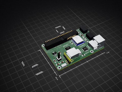
uli/basicengine-pcb
Schematics and PCB layout for the BASIC Engine home computer


It measures 100.3 × 101.6 mm and has 2 copper layers, 1.6 mm thick.
75 parts, built around the LT1491AIN and AMS1117. The full list of its parts is on this page, with links to each part's symbol and footprint where PCBKit's library has them.
From the Spiros7bit/SSVEP-Based-Brain-Computer-Interface-BCI repository on GitHub, at the commit this page was made from: the board is eeg_pcb_v4/eeg_pcb_v4.kicad_pcb and its schematic eeg_pcb_v4/eeg_pcb_v4.kicad_sch. PCBKit opens the board in the browser, with nothing to install.
Its repository states no licence, so its author keeps all rights: ask Spiros7bit before reusing the design.