2 layers175.8 × 184.8 mm
SofleKeyboard
josefadamcik/SofleKeyboard
A split keyboard based on Lily58, Crkbd and Helix keyboards
87 parts2.6k

 Slavfot/gallium-keyboard6
Wireless Ergonomic Mechanical Keybard
Nukleon Keyboard is an open-source printed circuit board by Slavfot, from the Slavfot/gallium-keyboard repository on GitHub, published under the GPL-3.0 licence. It is a 2-layer board of 133.4 × 113.9 mm with 87 parts on 90 nets, routed with 1,752 tracks and 114 vias.
Its parts include 31 diodes and 31 switches. It belongs with the keyboards and input boards of this library.
The Gallium Keyboard is a Wireless Ergonomical Split Keyboard.
I have a problem with the keyboard that i have opened an issue at the redox Github. https://github.com/mattdibi/redox-keyboard/issues/55 The problem is interference making it hard to use in some environments. I use it daily at work and it works really good except sometimes i have to replug the usb receiver at startup to get a good connection. At home it is almost unusable because of interference. Missing key presses and high latency. I'm trying to solve this and will post an update when i find a stable solution for the wireless communication.
At the moment I'm working on a micro pro version wich will make it possible to use the nice!nano bluetooth module with it instead. My goal is to stock these and sell as kits togehter with 3D printed case. And even aluminium cases in GB.
| Qty | Item | Notes |
|---|---|---|
| 62 | Cherry MX compatible switches | |
| 62 | Kailh MX hot swap sockets (optional) | |
| 2 | Gallium Wireless PCBs | |
| 2 | YJ-14015 modules (Core51822B clones) | aliexpress or ebay |
| 62 | 1N4148 diodes | SMD 1N4148 SOD-123 diodes can also be used |
| 2 | Keystone 3034 SMT battery holders | digikey |
| 2 | PCM12SMTR SMT slide switches | digikey |
| 2 | Right angle 0.1" header (1x4pin) |
| Qty | Item | Notes |
|---|---|---|
| 1 | Redox receiver PCB | |
| 1 | YJ-14015 module (Core51822B clone) | aliexpress or ebay |
| 1 | Arduino 5v 16MHz Pro Micro compatible microcontroller | [aliexpress or ebay] |
| 1 | 1117 3.3v regulator in SOT223 | digikey |
| 2 | 330 Ohm 0805(2012 metric) SMD resistors | Default configuration. Values depends on LED color, see below |
| 2 | 220 Ohm 0805(2012 metric) SMD resistors | Default configuration. Values depends on LED color, see below |
| 3 | 1.5k Ohm 0805(2012 metric) SMD resistors | Default configuration. See below |
| 1 | Red 0805(2012 metric) SMD standard LED | Default configuration. |
| 1 | Blue 0805(2012 metric) SMD standard LED | Default configuration. |
| 1 | Green 0805(2012 metric) SMD standard LED | Default configuration. |
| 1 | White 0805(2012 metric) SMD standard LED | Default configuration. |
| 1 | Through hole momentary switch | Dimensions 6mm x 6mm x 4.3mm |
| 1 | Right angle 0.1" header (1x4pin) | |
| 2 | Straight hot swap 0.1" header (1x6pin) | Use wire from diods as legs |
:information_source: You can also use the Mitosis receiver since it's almost identical, or you can build a receiver on your own.
:warning: To program the YJ-14015 MCUs you need an ST-Link v2 programmer, these can be found on eBay or Aliexpress for as little as 2$ shipped. See picture below.
If you want to customize your LEDs color or save a few bucks by ordering the LED all the same color you can refer to this section for choosing the correct resistor values. Otherwise you can refer to the default configuration.
There are two sets of resistor that you need for the receiver.
R1, R2 and R3): anything between 1.5k Ohm and 4.7k Ohm is good.R4,R6,R7 and R8): see the following table.| LED color | Vf | Suggested resistor value |
|---|---|---|
| Red | 1.7V | 330 Ohm |
| Yellow | 2.1V | 330 Ohm |
| Blue | 3.2V | 220 Ohm |
| Green | 2.2V | 330 Ohm |
| White | 3.6V | 220 Ohm |
Depending on the color you choose to use you should use the resistor listed above.
Here you can find the default configuration for the receiver assembly.
| Label | Component |
|---|---|
| D1 | Red LED |
| D2 | Blue LED |
| D3 | Green LED |
| D4 | White LED |
| R4 | 330 Ohm resistor |
| R6 | 220 Ohm resistor |
| R7 | 330 Ohm resistor |
| R8 | 220 Ohm resistor |
| R1 | 1.5k Ohm resistor |
| R2 | 1.5k Ohm resistor |
| R3 | 1.5k Ohm resistor |
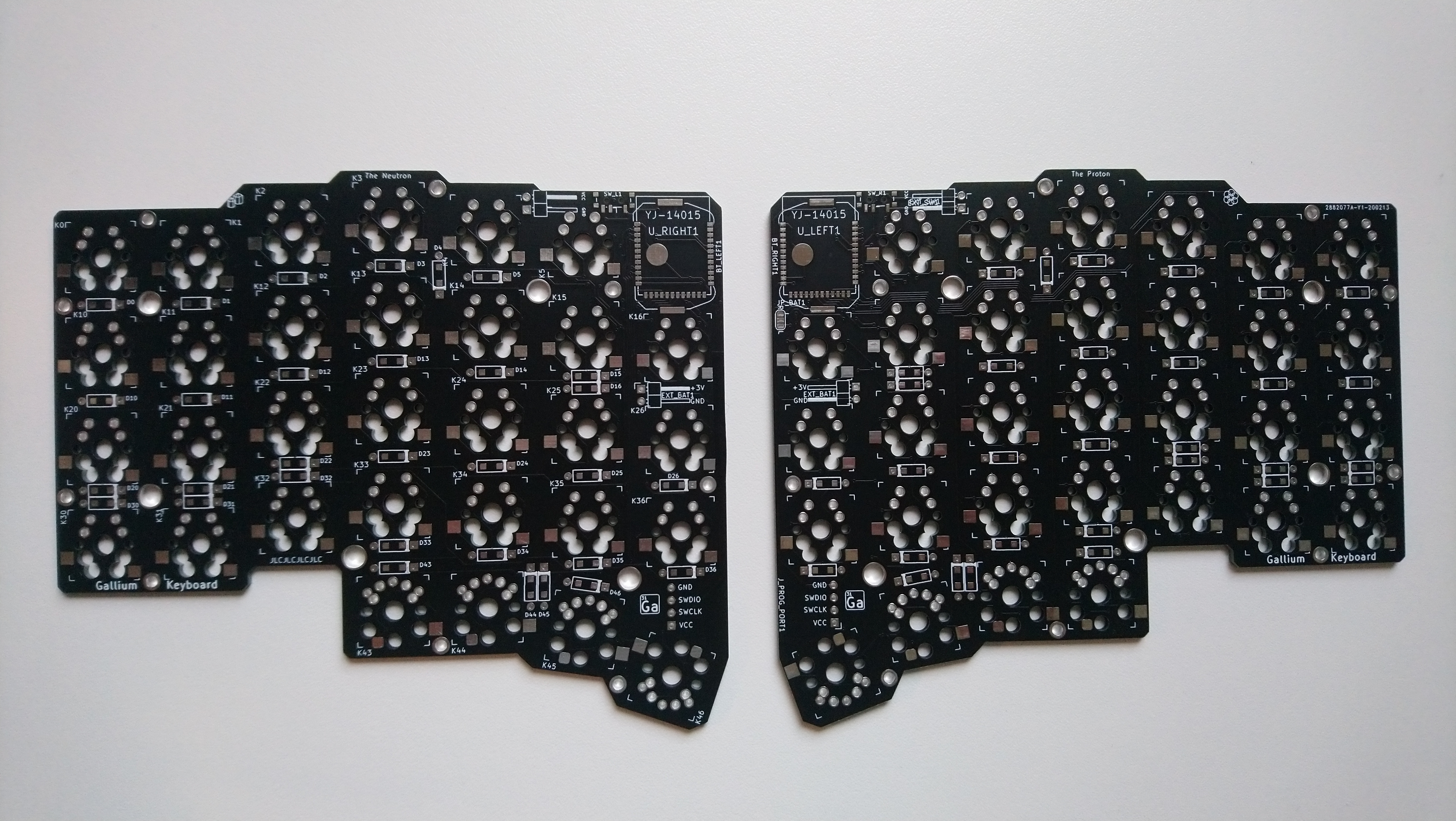
Assembly steps:
Wet one pad with solder. Position the component and hold the component in place with a tweezer. Heat up the wet pad and let cool, this should fix the component. Re-heat and adjust the position if the component isn't placed perfect. Be sure not to heat to long wich may damage the PCB or the component. Solder the rest of the pads like normal.
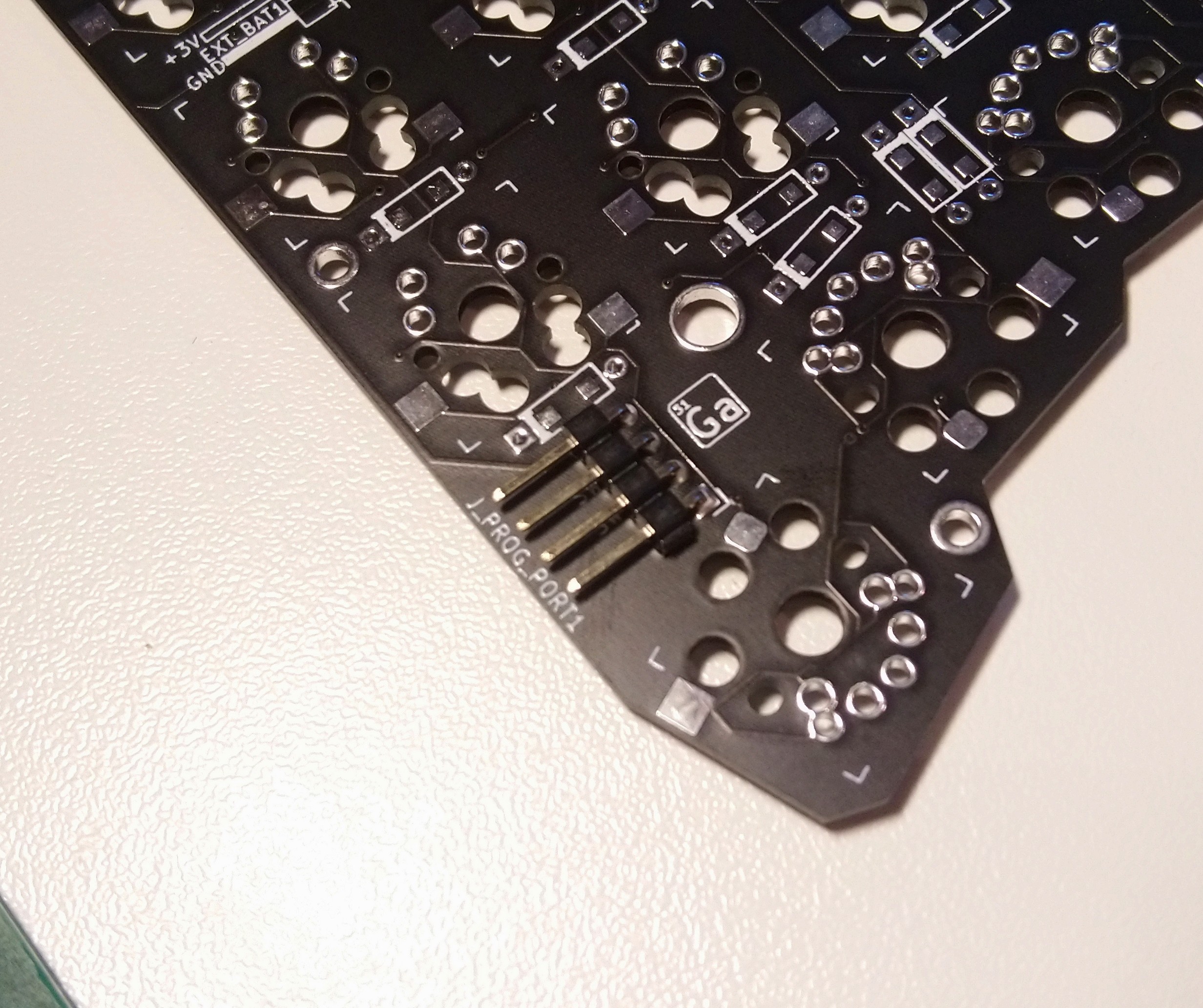
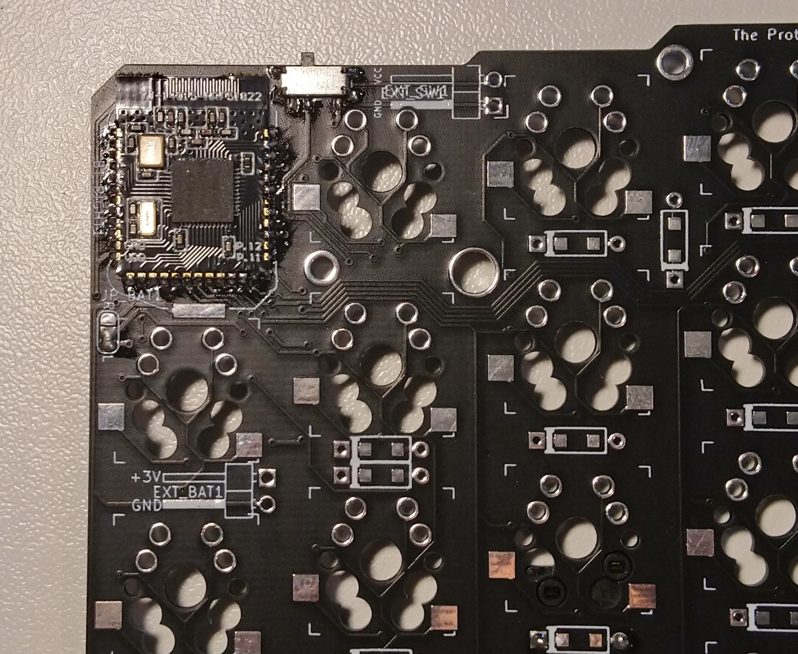
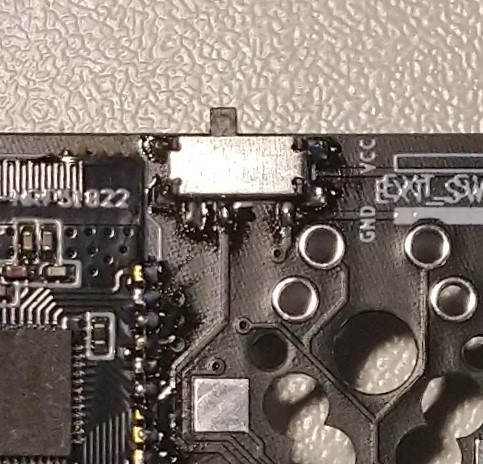
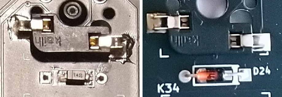
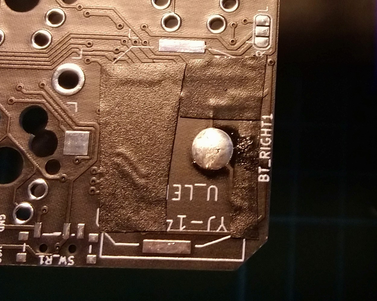
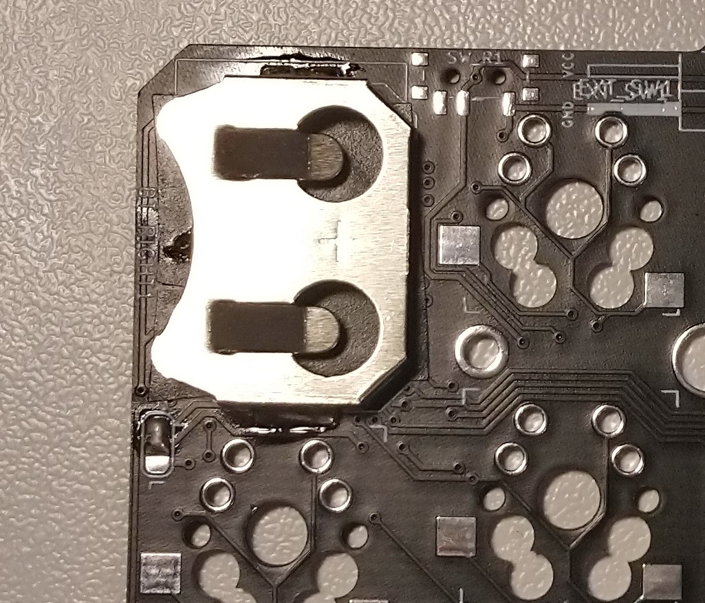

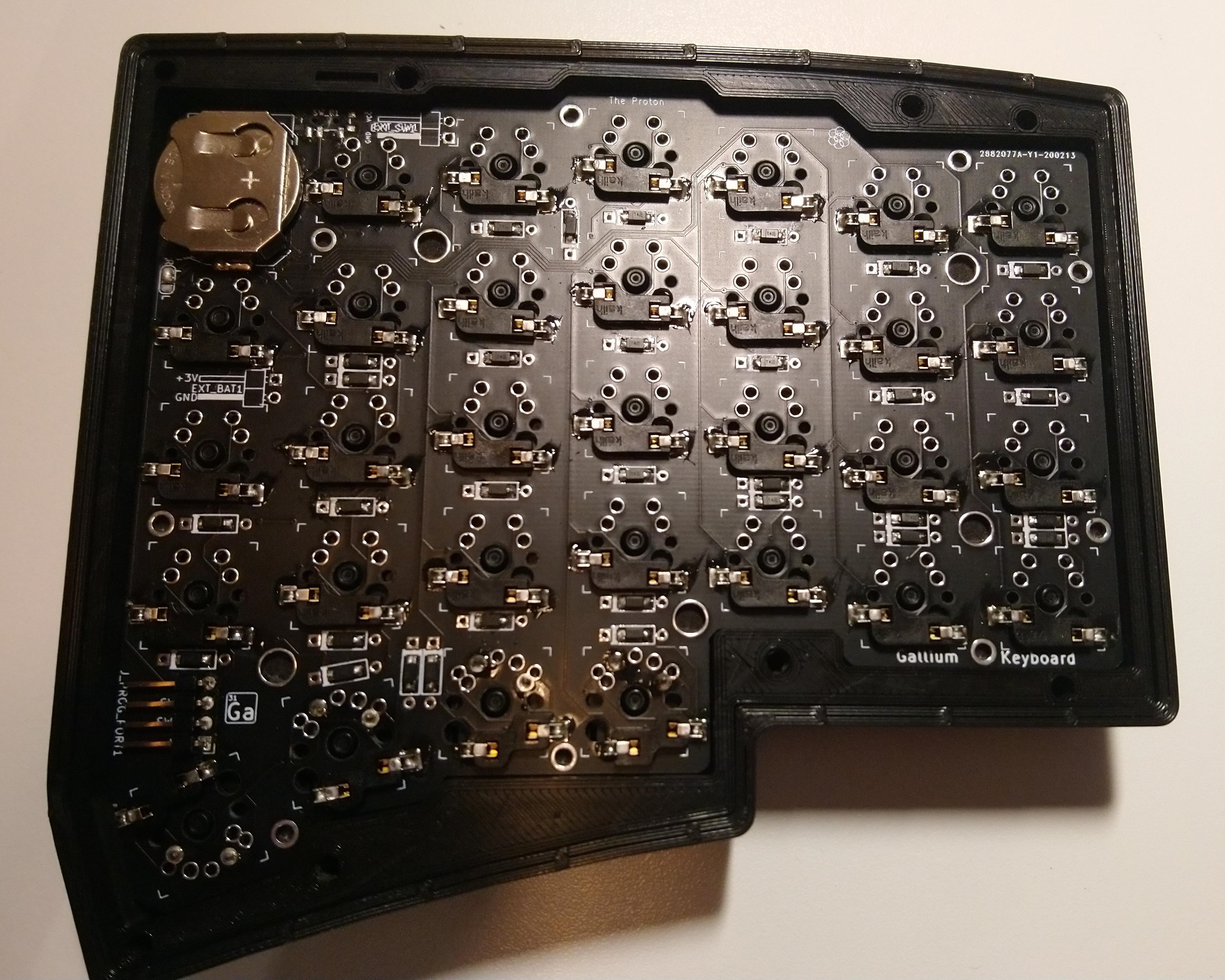
The receiver assembly is pretty straightforward i suggest soldering it in this order:
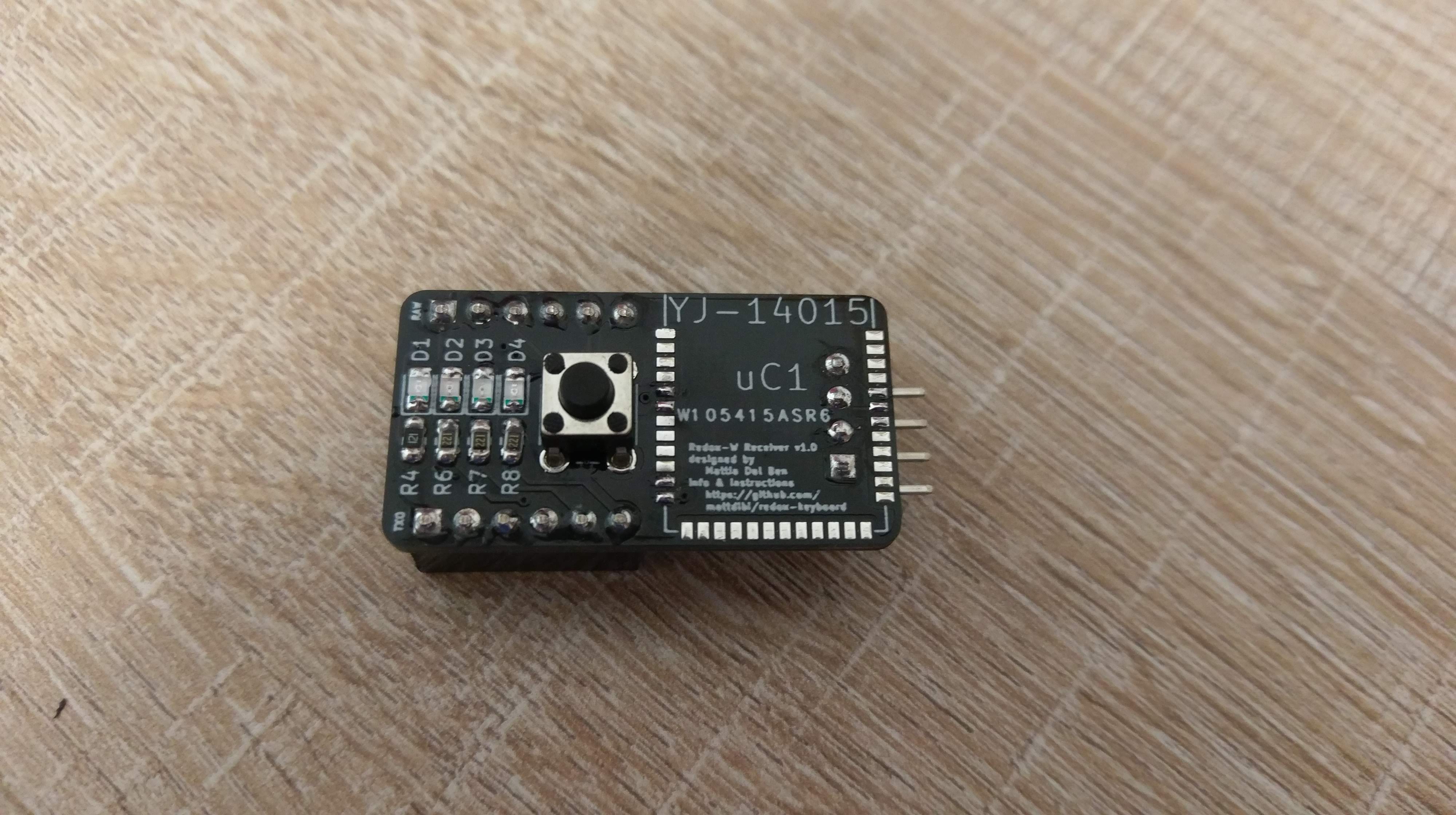

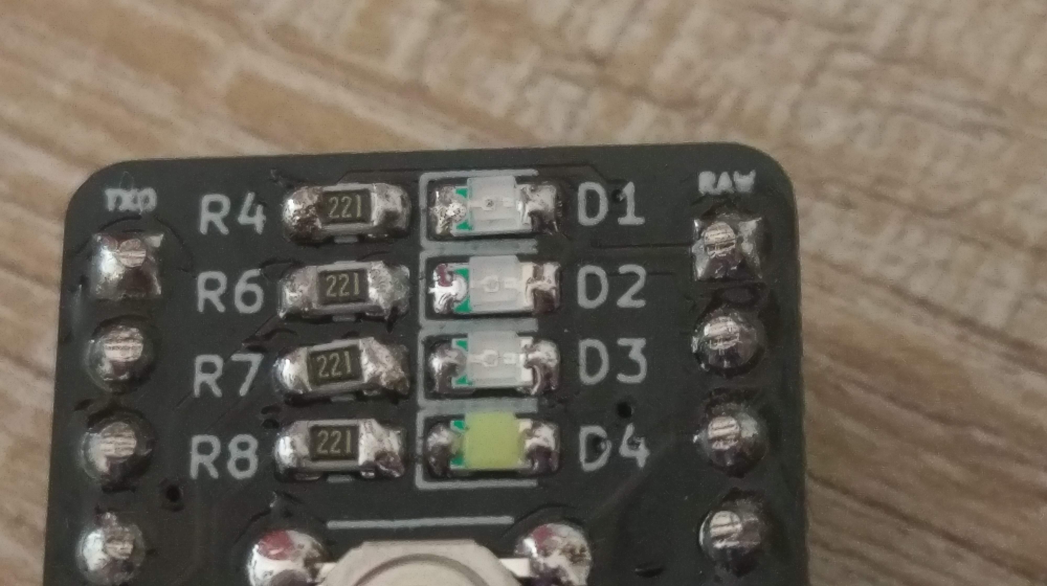
:information_source: Please note that here I installed 220 Ohm resistors because I used only blue and white LEDs as I only had those laying around. You should use the resistor values suggested here or follow the default configuration.
Basics: The Gallium keyboard works similarly to the Mitosis keyboard: we have two transmitters responsible for scanning the two matrices, which then transmit the matrix status through the Gazel protocol to the receiver. The receiver is another YJ-14015 which receives the two matrix scans and send it through serial to the Arduino Pro Micro. The Pro Micro is responsible for running QMK and converting the bytes received by the YJ-14015 into actual keystrokes.
Firmware sources available here: https://github.com/slavfot/gallium-firmware.
You'll need to upload the firmware to the corresponding MCUs as per the following diagram:
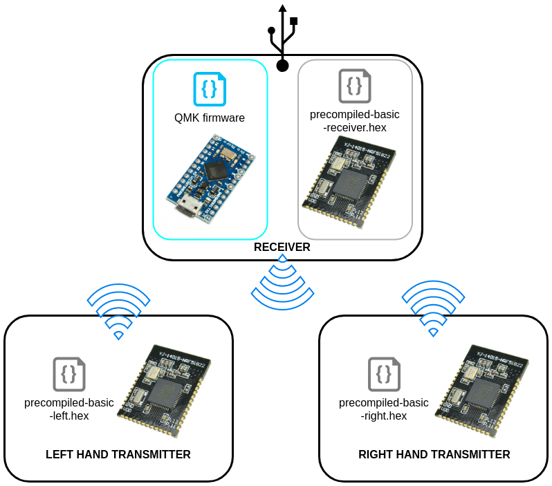
Note that you'll need to upload the firmware for the YJ-14015 only once. Everything related to the keymap is handled by the Arduino Pro Micro and QMK Firmware, that's what you will need to modify to update the keymap.
Let's start by uploading the QMK firmware on the Arduino, this will help us in diagnosing problems early on. The Gallium uses QMK for its firmware, follow the QMK installation instructions here, then compile and burn the firmware as follows:
$ cd path/to/qmk_firmware
$ make gallium:default:avrdude
You can find the code for the Gallium here: QMK - Gallium Wireless keyboard.
In the Gallium Keyboard firmware repository I added some pre-built hex files with the default keymap for testing purpose.
You'll need only to flash the pre-built .hex files to the corresponding MCUs, for this you'll need an STLinkV2 debugger.
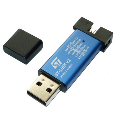
https://freddiechopin.info/en/download/category/4-openocd
Unzip anywhere.
But for ease of use in CMD i put it in C:\OpenOCD
Hook up the ST-Link debugger to the receiver/keyboard board you assembled without the Arduino. You need to connect only the VCC, GND, SWDIO and SWCLK pins of the board like this:
| ST-Link Debugger | Receiver board |
|---|---|
| 3.3V | VCC |
| GND | GND |
| SWCLK | SWCLK |
| SWDIO | SWDIO |
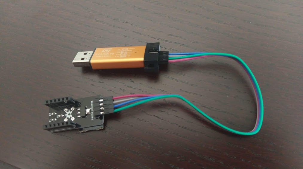
Then plug in the ST-Link debugger into your PC.
\openOCD\binFirst make sure you are in the right drive.
If you need to change drive then type the drive letter only likes this "d:"
after that you can navigate in that drive.
Commands to navigate with:
Tips: Press the tab button to automaticaly complete the directorys name while typing the cd command.
Download Gallium-keyboard master zip and unzip anywhere but for ease of use put it in C:
https://github.com/Slavfot/gallium-keyboard/archive/master.zip
Launch an openOCD server session with this command:
openocd -s C:\OpenOCD\scripts\ -f interface/stlink-v2.cfg -f target/nrf51.cfgThis line is written as if the OpenOCD folder is located at C:\
Change accordingly to where you have it located.
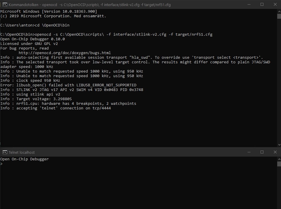
It should give you an output ending in:
Info : nrf51.cpu: hardware has 4 breakpoints, 2 watchpointsOtherwise you likely have a loose or wrong wire.
Example for the file path if the .hex file is located in C:\Gallium-keyboard\precompiled
/gallium-keyboard/precompiled/
Connect to the OpenOCD session:
telnet localhost 4444From the factory, these chips need to be erased:
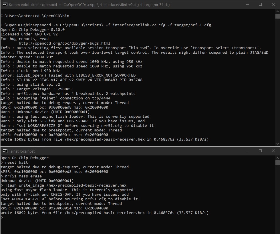
reset halt

nrf51 mass_erase
Write file to wireless-module
Use this command to flash the receiver:
flash write_image /gallium-keyboard/precompiled/precompiled-basic-receiver.hexFor each keyboard half flash with either of these files
flash write_image /gallium-keyboard/precompiled/precompiled-basic-left.hexor
flash write_image /gallium-keyboard/precompiled/precompiled-basic-right.hexThis is how it should look when you connect to telnet:
The whole process should look like this:
Congratulations you have now flashed your Gallium Keyboard!
Note: Tested on Ubuntu 16.04 and 18.04 but you should be able to find alternatives on all distros.
sudo apt update
sudo apt install openocdOpen a terminal and download this repository wherever you want. We'll need the gallium/firmware folder content.
git clone https://github.com/slavfot/gallium-keyboard.gitor
wget https://github.com/slavfot/gallium-keyboard/archive/master.zipcd path/to/repository/gallium-keyboard/firmware/
sudo cp 49-stlinkv2.rules /etc/udev/rules.d/Hook up the ST-Link debugger to the receiver/keyboard board you assembled without the Arduino. You need to connect only the VCC, GND, SWDIO and SWCLK pins of the board like this:
| ST-Link Debugger | Receiver board |
|---|---|
| 3.3V | VCC |
| GND | GND |
| SWCLK | SWCLK |
| SWDIO | SWDIO |
Then plug in the ST-Link debugger into your PC.
In a new terminal window launch an OpenOCD server session by issuing the following command:
openocd -s /usr/local/Cellar/open-ocd/0.8.0/share/openocd/scripts/ -f interface/stlink-v2.cfg -f target/nrf51.cfgThis should give the following output:
Info : nrf51.cpu: hardware has 4 breakpoints, 2 watchpointsLeave this terminal window open.
There are three Wireless modules that need to be flashed with firmware: The receiver, left hand keyboard hand the right hand keyboard.
We can now issue the flashing commands. Open a terminal in the Gallium firmware folder.
cd path/to/repository/gallium-keyboard/firmware/From the factory, these chips need to be erased:
echo reset halt | telnet localhost 4444
echo nrf51 mass_erase | telnet localhost 4444
You should be seeing some movement in the OpenOCD terminal window, and you desktop should be looking somewhat like this:

Now we can upload the receiver firmware onto the MCU.
echo reset halt | telnet localhost 4444

!Choose one!:
receiver:
echo flash write_image `readlink -f precompiled-basic-receiver.hex` | telnet localhost 4444

Left hand keyboard:
echo flash write_image `readlink -f precompiled-basic-left.hex` | telnet localhost 4444

Right hand keyboard:
echo flash write_image `readlink -f precompiled-basic-right.hex` | telnet localhost 4444

and last:
echo reset | telnet localhost 4444
You should be looking at something like this:

Now close the OpenOCD session (use Ctrl-C) and you're done with the flashing. Repeat these steps for all three modules.
When all three modules have been flash you are done! Congratulations, You flashed the Gallium Keyboard!
mattdibi about the battery consumption:
With a CR2032 with 220mAh we can expect at least 880 hours of continuous typing on the keyboard before needing to change the batteries. Keep in mind that when you're not typing (500ms without key presses is the time interval needed for the keyboard) the transmitters go into deep sleep mode and draw only 2.7uA. So for an everyday use (4 hours a day of continuous typing) you can expect a battery life of at least a year. Obviously your mileage may vary. Source and calculations: https://github.com/mattdibi/redox-keyboard/tree/master/redox-w#battery-usage
| Qty | Value | Footprint | References |
|---|---|---|---|
| 31 | D | Antons_footprints:D_SOD123_axial_both_sides | D0, D1, D2, D10, D11, D12, D13, D14, D15, D16, D20, D21, D22, D23, D24, D25 +15 |
| 27 | KEYSW | Antons_footprints:SW_Cherry_MX_1.00u_PCB_Hot_Swap_Optional | K0, K1, K2, K10, K11, K12, K13, K14, K15, K16, K20, K21, K22, K23, K24, K25 +11 |
| 9 | MountingHole | MountingHole:MountingHole_2.2mm_M2_ISO7380_Pad | H1, H2, H3, H4, H5, H9, H10, H12, H14 |
| 5 | MountingHole | Antons_footprints:Thru_hole_for_M2_standoff_space | H6, H7, H8, H11, H13 |
| 4 | KEYSW | Antons_footprints:PG1350_socket_reversible_MX_Holtite | K43, K44, K45, K46 |
| 2 | Conn_01x02 | Antons_footprints:PinHeader_1x02_P2.54mm_Horizontal_double_side | EXT_BAT1, EXT_SW1 |
| 2 | SW_SPDT | Antons_footprints:SW_SPDT_PCM12 | SW_L1, SW_R1 |
| 2 | YJ-14015 | Antons_footprints:MY-YJ-14015-Module | U_LEFT1, U_RIGHT1 |
| 1 | |||
| 1 | Battery_Cell | Antons_footprints:BatteryHolder_Keystone_3034_1x20mm_right | BT_RIGHT1 |
| 1 | Battery_Cell | Antons_footprints:BatteryHolder_Keystone_3034_1x20mm_left | BT_LEFT1 |
| 1 | Conn_01x04_Male | Connector_PinHeader_2.54mm:PinHeader_1x04_P2.54mm_Horizontal | J_PROG_PORT1 |
| 1 | SolderJumper_3_Open | Jumper:SolderJumper-3_P1.3mm_Open_RoundedPad1.0x1.5mm_NumberLabels | JP_BAT1 |
josefadamcik/SofleKeyboard
A split keyboard based on Lily58, Crkbd and Helix keyboards

ataradov/usb-sniffer
Low-cost LS/FS/HS USB sniffer with Wireshark interface


sabogalc/KiCad-Arduino-Boards
A collection of Arduino boards recreated from scratch in KiCad. Legacy USB connectors have been replaced with USB-C where applicable.
It measures 133.4 × 113.9 mm and has 2 copper layers, 1.6 mm thick.
87 parts. The full list of its parts is on this page, with links to each part's symbol and footprint where PCBKit's library has them.
From the Slavfot/gallium-keyboard repository on GitHub, at the commit this page was made from: the board is Kicad Files/0.1/Nukleon Keyboard.kicad_pcb. PCBKit opens the board in the browser, with nothing to install.
Its repository publishes it under the GPL-3.0 licence: you may reuse it on that licence's terms (keep the author's notice, and for a copyleft licence share your changes alike).