
2 layers56.5 × 64.8 mm
OPL2 VGM Player
AidanHockey5/YM3812_VGM_Player
A Video Game Music player based on the YM3812 (OPL2) and Teensy 3.5
14 parts72AGPL-3.0
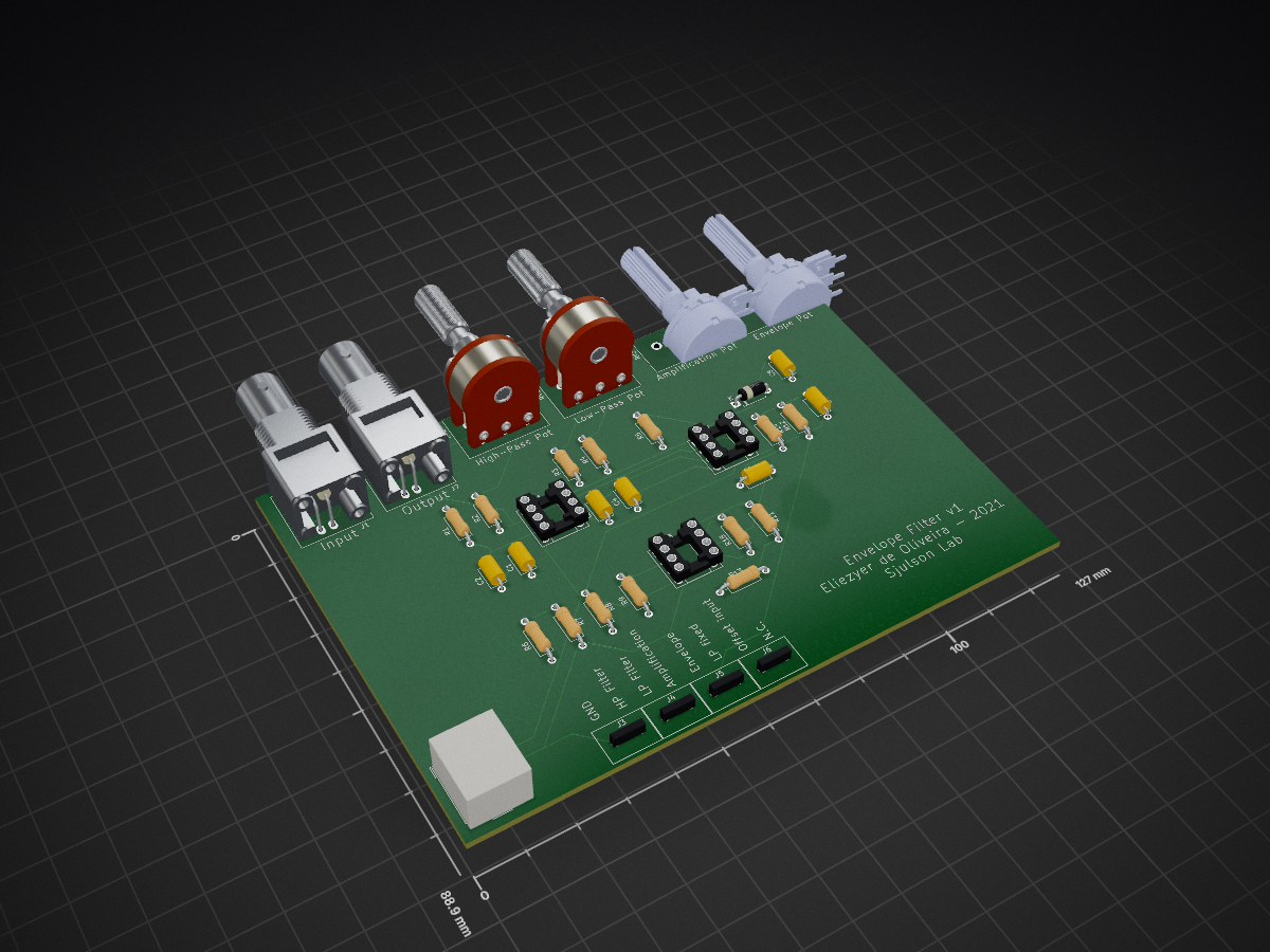
 SjulsonLab/analog_SWR_detection1
This repository contains the schematics and PCB design of a circuit that implements a set of filters for sharp wave-ripple detection. It consists of a band-pass filter followed by an envelope low-pass filter.
Analog SWR detection is an open-source printed circuit board by SjulsonLab, from the SjulsonLab/analog_SWR_detection repository on GitHub, published under the GPL-3.0 licence. It is a 2-layer board of 127 × 88.9 mm with 36 parts on 34 nets, routed with 264 tracks and 0 vias.
It is built around the LM358N. Its parts include 14 resistors, 7 capacitors, 7 connectors, 3 ICs and 1 diode.
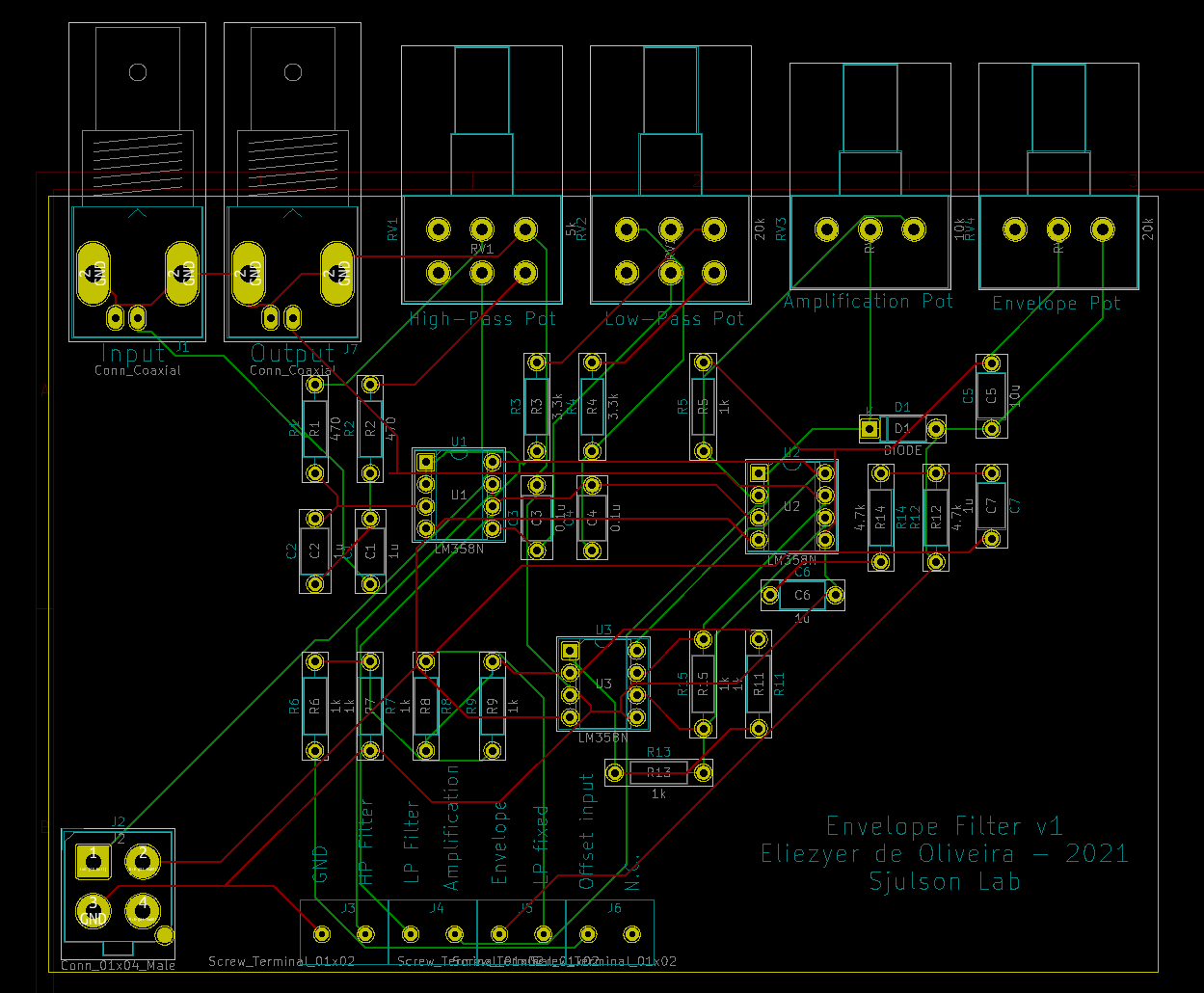
This repository contains the schematics and PCB design of a circuit that implements a set of filters for sharp wave-ripple detection. It consists of a band-pass filter followed by an envelope low-pass filter.
The circuit includes the possibility of offsetting the signal to use with the analog-digital converters of other devices for detection (Arduino and Raspberry Pi).
By adapting the components of this circuit, you can detect other events, such as gamma oscillations or spindles.
The main content of this repository is found in the folder analaog_SWR_detection. Everything was designed using the free software KiCad
The file analog_swr_dection.sch contains the circuit schematics, and the file analog_SWR_detection.kicad_pcb can be used to fabricate a printed circuit board.
| Qty | Value | Footprint | References |
|---|---|---|---|
| 8 | 1k | Resistor_THT:R_Axial_DIN0207_L6.3mm_D2.5mm_P10.16mm_Horizontal | R5, R6, R7, R8, R9, R11, R13, R15 |
| 4 | 1u | Capacitor_THT:C_Axial_L5.1mm_D3.1mm_P7.50mm_Horizontal | C1, C2, C6, C7 |
| 4 | Screw_Terminal_01x02 | Connector:dual_screw_terminal | J3, J4, J5, J6 |
| 3 | LM358N | Package_DIP:DIP-8_W7.62mm_Socket | U1, U2, U3 |
| 2 | 0.1u | Capacitor_THT:C_Axial_L5.1mm_D3.1mm_P7.50mm_Horizontal | C3, C4 |
| 2 | 3.3k | Resistor_THT:R_Axial_DIN0207_L6.3mm_D2.5mm_P10.16mm_Horizontal | R3, R4 |
| 2 | 4.7k | Resistor_THT:R_Axial_DIN0207_L6.3mm_D2.5mm_P10.16mm_Horizontal | R12, R14 |
| 2 | 470 | Resistor_THT:R_Axial_DIN0207_L6.3mm_D2.5mm_P10.16mm_Horizontal | R1, R2 |
| 2 | Conn_Coaxial | Connector_Coaxial:BNC_Amphenol_B6252HB-NPP3G-50_Horizontal | J1, J7 |
| 1 | 10k | Potentiometer_THT:Potentiometer_Alps_RK163_Single_Horizontal | RV3 |
| 1 | 10u | Capacitor_THT:C_Axial_L5.1mm_D3.1mm_P7.50mm_Horizontal | C5 |
| 1 | 20k | Potentiometer_THT:Potentiometer_Alps_RK163_Single_Horizontal | RV4 |
| 1 | 20k | Potentiometer_THT:Potentiometer_Alps_RK163_Dual_Horizontal | RV2 |
| 1 | 5k | Potentiometer_THT:Potentiometer_Alps_RK163_Dual_Horizontal | RV1 |
| 1 | Conn_01x04_Male | Connector_Molex:Molex_Mega-Fit_76829-0104_2x02_P5.70mm_Vertical | J2 |
| 1 | DIODE | Diode_THT:D_A-405_P7.62mm_Horizontal | D1 |
AidanHockey5/YM3812_VGM_Player
A Video Game Music player based on the YM3812 (OPL2) and Teensy 3.5


kr4fty/DiySolderingStation
Diy Soldering Stations with Atmega (Arduino UNO). Firmware and hardware design included


It measures 127 × 88.9 mm and has 2 copper layers, 1.6 mm thick.
36 parts, built around the LM358N. The full list of its parts is on this page, with links to each part's symbol and footprint where PCBKit's library has them.
From the SjulsonLab/analog_SWR_detection repository on GitHub, at the commit this page was made from: the board is PCB/analog_SWR_detection/analog_SWR_detection/analog_SWR_detection.kicad_pcb. PCBKit opens the board in the browser, with nothing to install.
Its repository publishes it under the GPL-3.0 licence: you may reuse it on that licence's terms (keep the author's notice, and for a copyleft licence share your changes alike).