2 layers37 × 47.3 mm
MicroPicoDriveCartridge
Silveriomrs/micropicodrive
Internal Microdrive replacement for the Sinclair QL
11 parts7MIT

 Silveriomrs/micropicodrive7
Internal Microdrive replacement for the Sinclair QL
MicroPicoDrive is an open-source printed circuit board by Silveriomrs, from the Silveriomrs/micropicodrive repository on GitHub, published under the MIT licence. It is a 2-layer board of 63.1 × 56.1 mm with 31 parts on 53 nets, routed with 288 tracks and 135 vias.
It is built around the SN74LVC1T45DBVRE4, TXU0304QPWRQ1 and B240. Its parts include 7 capacitors, 5 ICs, 4 resistors, 2 connectors and 1 diode. It belongs with the RP2040 boards of this library.


An internal replacement for the Sinclair QL Microdrive
UPDATE 12/08/2026
[!NOTE] New revisions of the driver & cartridges with extra EMI & electrical protection and improving signals. Firmware revision 0.14 improved & stable. Firmware & driver tested, tested last cartridge sub-version 'e' for 4 weeks. Added 3D case (STL) created by Jbizze for short cartridge version to its link.
[!TIP] All material (Gerbers, BOM, etc) & user guides at the bottom of the page.
This branch is for the new 1.4 version of the MicroPicoDrive. This version was created by Silverio MRS (AKA Popopo) from Dr. Gusman's original version.
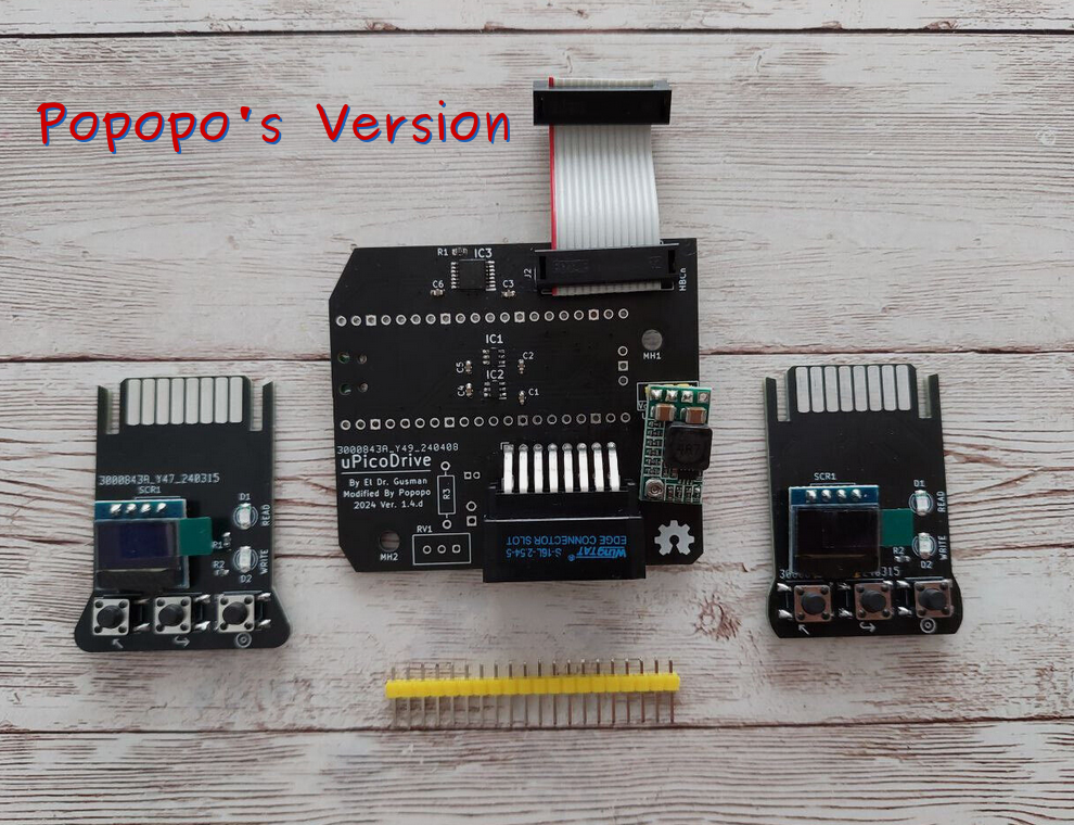
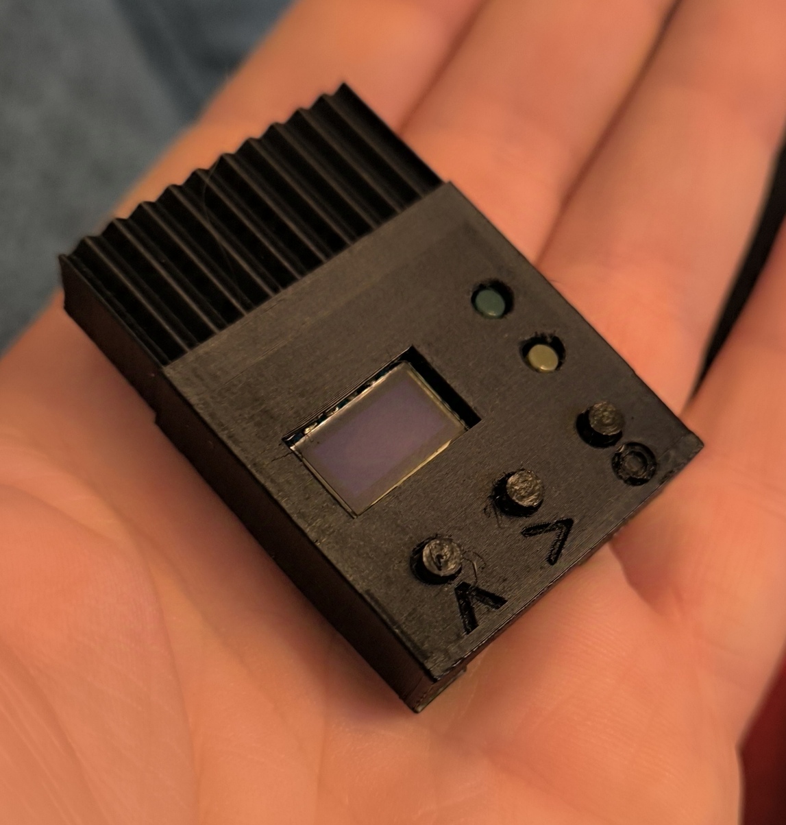
The image above shows the main driver unit and the 2 cartridges versions with long and short wings (handles). Long wings allows to manipulate the cartridge easily reducing mechanical pressure. Shorts instead gives an old fashion shape and allows to be stored into the old (used) black boxes of QL time. Also wearing the 3D case created by Jbizze for the short version cartridge.
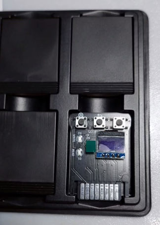
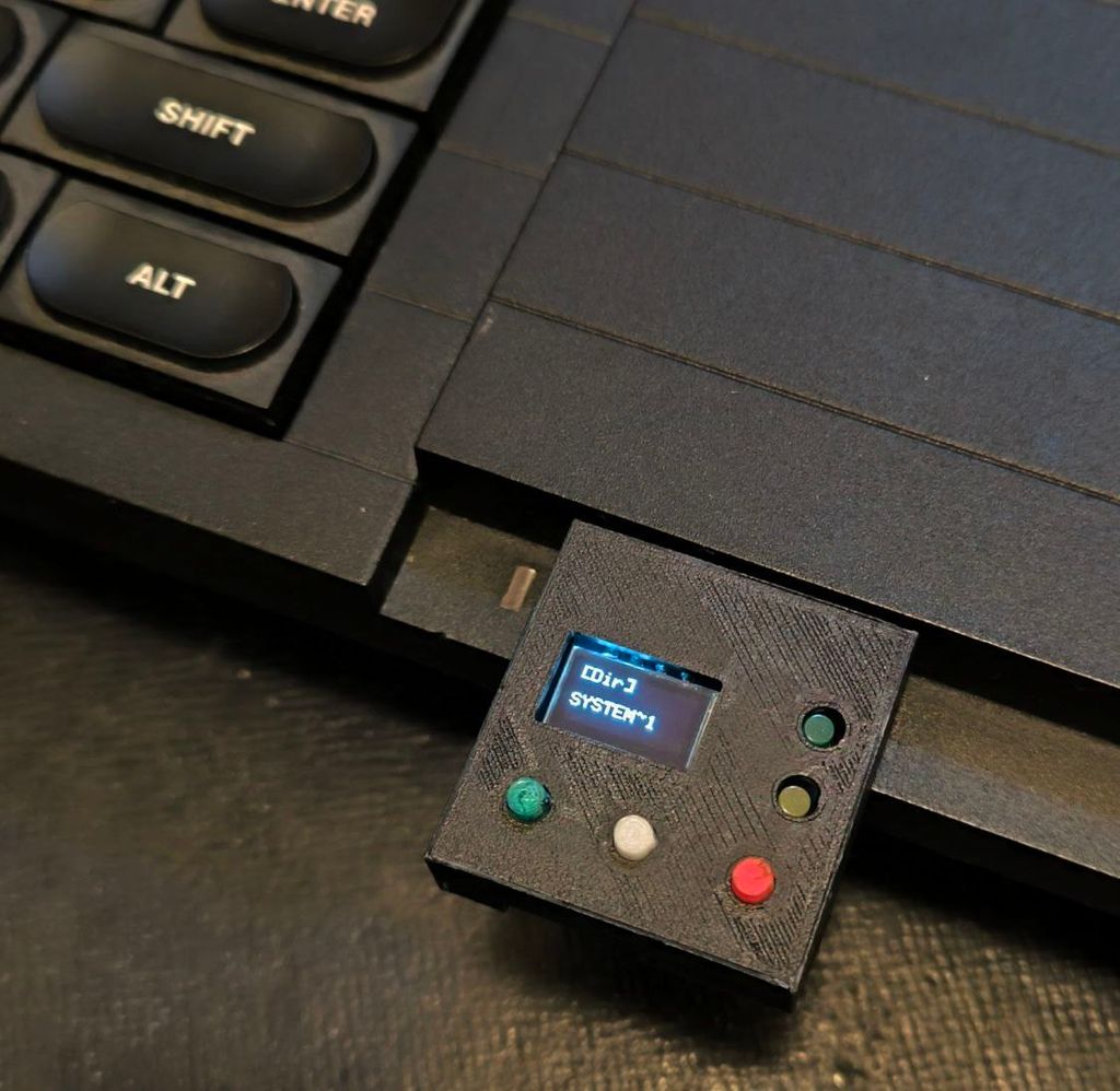
The next link is a fast view with a demo of the device Short video demo on Youtube.
Schema of the driver unit that goes inside the QL.
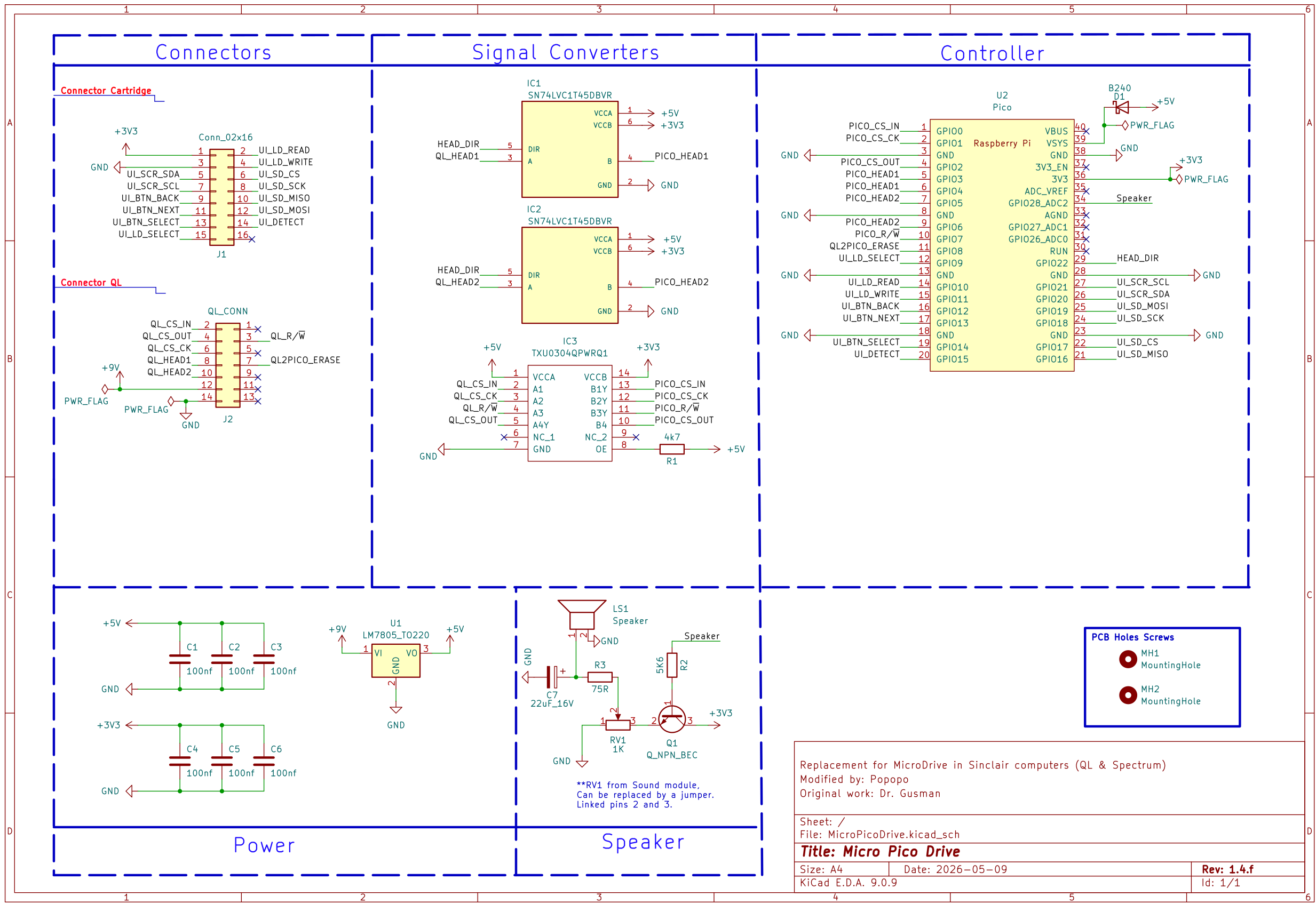
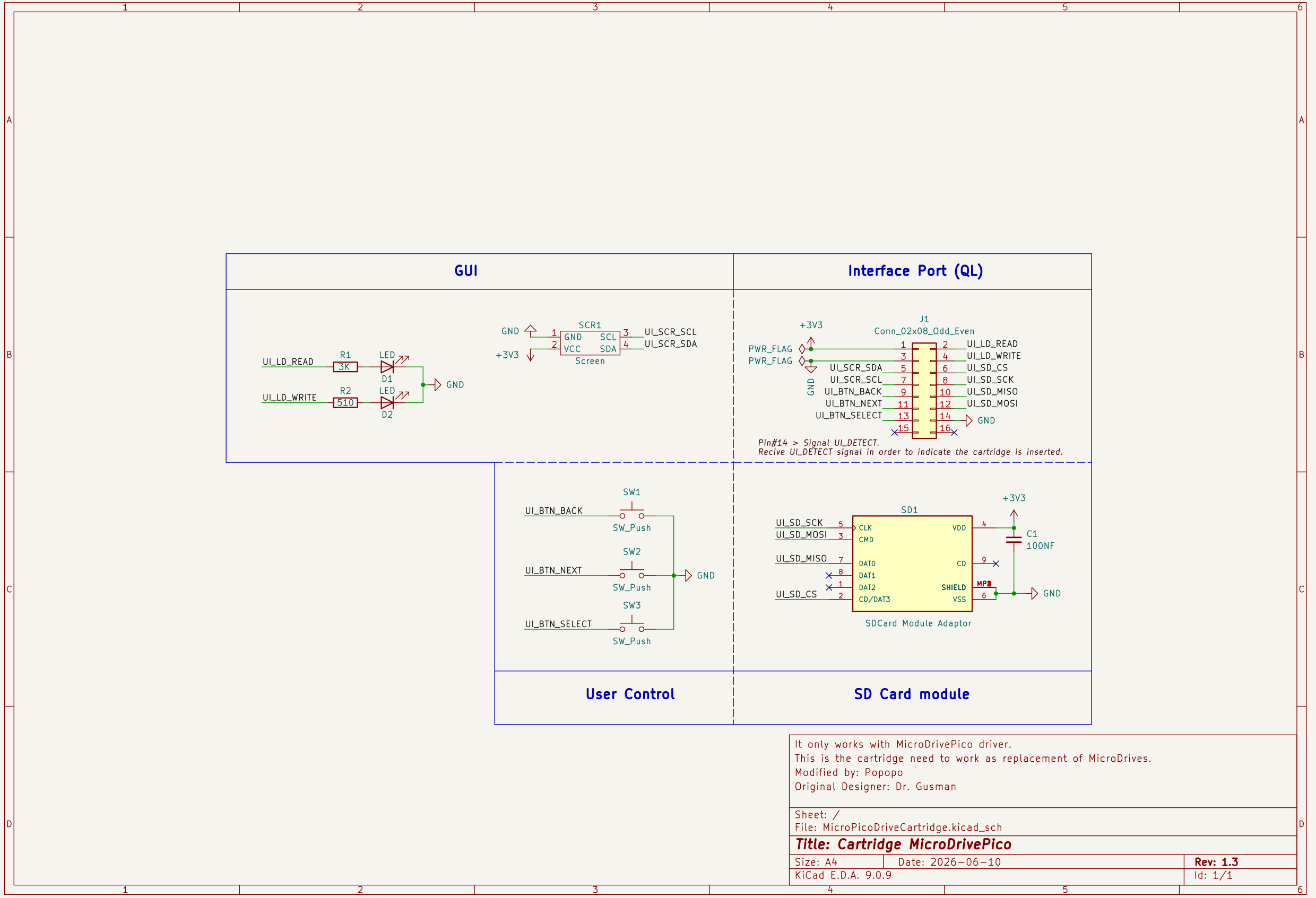
Schema of the cartridge that host the microSD and interact with the user.
The project was born to give a solution to the old ZX Microdrive data systems that relies on tape technology. Due to all those system are more than 50 years old and doesn't exist replacements. This system needed a modern replacement stable, very easy to use, flexible and cheap.
The solution presented relay on Hardware and Software combination. With an OpenSource philosophy that could be easily be continued by thirds parties if needed.
The OpenSource & OpenHardware philosophy also responds to the main idea of allowing everyone to built at any time with inexpensive materials, modify or implements different features.
The project was born with the simple goal to be something that anyone could afford and built, what was exceed by far. Yet, there were some details that make the solution not so universal for everyone (IMO). Here is where our story begins.
The point is to exploit all the potential of the concept, increasing the number of features of the device, closer to the Gotek concept but powered up with a lot of amazing and desired features.
The first approach was a full success. Whatever in some design points it was limited:
Not only the hardware have been re-shaped, but the code/firmware has been refactored, documented (even more) and modularized in a way that the skills requirements to modify it, become affordable with lower programming skill than before.
It makes sense if the idea is to get chances of scalability and maintenance by the community or recycle the code/hardware in other similar projects.
New 1.4 design changes:
Majority of users find the device functional and accomplish their expectations, however still it keeps some nice surprises to powering it up. All of then can be activated optionally (opt).
Software/firmware
Hardware
The next videos were made in order to make easier to everyone the understanding about the integration and use on Sinclair QL systems.
To download and make the devices on your own using my design you can access to the Gerbers and Firmwares at the release section: Releases Gerbers & Firmware
For detailed information about revisions of drivers or cartridges go to see: Gerbers Descriptions Section
For i/BOM check directory: Schmems & i/BOMs
For 3D case created by Jbizze for short cartridge version: STL from Thingverse or to Download directly: Releases Gerbers & Firmware
| Qty | Value | Footprint | References |
|---|---|---|---|
| 6 | 100nf | Capacitor_SMD:C_0603_1608Metric | C1, C2, C3, C4, C5, C6 |
| 4 | MountingHole | MH_S1, MH_S2, MH_S3, MH_S4 | |
| 2 | MountingHole | MicroPicoDrive_Driver:MountingHole_3.5mm_safe_screw_area | MH1, MH2 |
| 2 | SN74LVC1T45DBVR | MicroPicoDrive_Driver:SOT95P280X145-6N | IC1, IC2 |
| 1 | 1K | Resistor_SMD:R_0603_1608Metric | R4 |
| 1 | 1K | Potentiometer_THT:Potentiometer_Bourns_3296W_Vertical | RV1 |
| 1 | 22uF_16V | Capacitor_THT:CP_Radial_D4.0mm_P1.50mm | C7 |
| 1 | 4k7 | Resistor_SMD:R_0603_1608Metric | R1 |
| 1 | 5K6 | Resistor_SMD:R_0603_1608Metric | R2 |
| 1 | 75R | Resistor_THT:R_Axial_DIN0207_L6.3mm_D2.5mm_P10.16mm_Horizontal | R3 |
| 1 | B240 | Diode_SMD:D_SMB | D1 |
| 1 | Conn_02x16 | MicroPicoDrive_Driver:Edge_connector_02x08 | J1 |
| 1 | KiCad-Logo2_5mm_SilkScreen | Symbol:KiCad-Logo2_5mm_SilkScreen | Log_KiCad |
| 1 | LM7805_TO220 | Package_TO_SOT_THT:TO-220-3_Vertical | U1 |
| 1 | LOGO | MDP_Footprints:QR_Code_MDP | G*** |
| 1 | OSHW-Symbol_6.7x6mm_SilkScreen | Symbol:OSHW-Symbol_6.7x6mm_SilkScreen | Log_OpenHardware |
| 1 | Pico | MicroPicoDrive_Driver:RPi_Pico_SMD_TH | U2 |
| 1 | QL_CONN | MicroPicoDrive_Driver:CONN_IDC_2x7 | J2 |
| 1 | Q_NPN_BEC | Package_TO_SOT_SMD:SOT-23W | Q1 |
| 1 | Speaker | Connector_PinHeader_2.54mm:PinHeader_1x02_P2.54mm_Vertical | LS1 |
| 1 | TXU0304QPWRQ1 | MicroPicoDrive_Driver:TXU0304QPWRQ1 | IC3 |
Silveriomrs/micropicodrive
Internal Microdrive replacement for the Sinclair QL

gusmanb/micropicodrive
Internal microdrive replacement for the Sinclair QL

arleybls/micropicodrive-ng-hardware
KiCad hardware design for an internal Microdrive replacement for the Sinclair QL. The device emulates a Microdrive cartridge drive using a Raspberry Pi Pico (RP2040) and stores data on a microSD card, fitting in the…


bash227/ECG-Motor-Control-Power-Management-PCB
A multi-function PCB integrating biomedical signal acquisition (ECG), DC motor control, and advanced power management for wearable applications.


sitlesh/Ultra-Compact-STM32-Smart-Data-Logger-Gateway
KiCad-based 2-layer custom PCB design featuring an on-board Micro SD card slot (SPI), dual crystal oscillators (8MHz & 32.768kHz), and integrated power management. Includes production-ready Gerber and Drill files.


brengi/CESE-PCB
Curso de Diseño de Circuitos Impresos de la Carrera de Especialización en Sistemas Embebidos
It measures 63.1 × 56.1 mm and has 2 copper layers, 1.6 mm thick.
31 parts, built around the SN74LVC1T45DBVRE4, TXU0304QPWRQ1 and B240. The full list of its parts is on this page, with links to each part's symbol and footprint where PCBKit's library has them.
From the Silveriomrs/micropicodrive repository on GitHub, at the commit this page was made from: the board is Hardware 1.4 (By Popopo)/MicroPicoDrive/MicroPicoDrive.kicad_pcb and its schematic Hardware 1.4 (By Popopo)/MDP_Cartridge_Large/MicroPicoDriveCartridge.kicad_sch. PCBKit opens the board in the browser, with nothing to install.
Its repository publishes it under the MIT licence: you may reuse it on that licence's terms (keep the author's notice, and for a copyleft licence share your changes alike).