Skip to the content
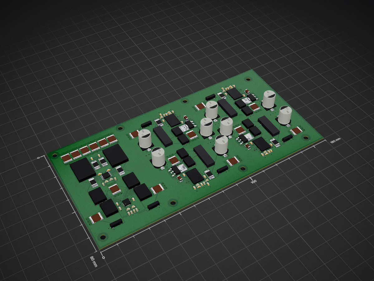
4 layers160 × 80 mmPowerboard, the printed circuit board in 3D

Files for SemuBot PCB design.

Size
160 × 80 mm
Copper layers
4
Thickness
0.62 mm
Parts
130
Nets
76
Pads
524
Tracks, vias
639, 356
Pours
138
Routed
Yes
KiCad
KiCad 10.0 (file 20260206)
Created
15 Jan 2024
Updated
29 Oct 2026

Overview

Powerboard is an open-source printed circuit board by SemuBot, from the SemuBot/semubot-electronics repository on GitHub. It is a 4-layer board of 160 × 80 mm with 130 parts on 76 nets, routed with 639 tracks and 356 vias.

Its parts include 60 capacitors, 28 resistors, 18 transistors, 6 ICs and 6 connectors.

README

wheelbase/README.md

Wheelbase

Overview

This project implements a 3-motor BLDC wheelbase controller using an STM32G4 microcontroller and three independent 3-phase gate-driver/MOSFET power stages, one per wheel.


Components

Microcontroller

  • STM32G474RET6 Main controller (LQFP-64).

BLDC Drivers

  • DRV8353FSRTAR (x3) 3-phase gate driver with integrated current-shunt amplifiers, one per motor.

MOSFETs

  • AON7262E (x18) N-channel MOSFETs for the power stage, 6 per motor (3-phase half-bridges).

Current Sensing

  • 9x 10 mΩ shunt resistors (2512 package), 3 per motor, read out through each DRV8353's integrated current-shunt amplifiers.

Voltage Regulation

  • RT9013-33GB 3.3V LDO regulator.

Power Input & Connectors

  • XT30PW-M Main DC power input connector.

  • MR30PW-M (x3) Motor phase power connectors, one per motor.

  • 10155435-00011LF (Amphenol) USB Type-C connector.

  • B5B-XH-A_LF(SN) (JST XH) (x6) 5-pin connectors for Hall/sensor inputs.

  • MTSW-104-09-L-S-400 (Samtec) 4-pin header, general purpose/debug I/O.

  • DS1013-10SSIB1 10-pin connector for general purpose I/O.

ESD / Overvoltage Protection

  • PRTR5V0U2X ESD protection for data lines (standard KiCad library part).
  • SMCJ33A 33V TVS diode for transient/overvoltage protection.
  • BZX84C3V3 3.3V zener diode.

Timing & Clock

  • X322516MLB4SI Crystal resonator for the STM32's HSE clock.

User Interface

  • 1x green + 4x red status LEDs.

Technical Summary

Power Stage

  • MOSFETs: 18x AON7262E (6 per motor)
  • Gate Drivers: 3x DRV8353FSRTAR
  • Current Sense Resistors: 9x 10mΩ (2512 package), read via the DRV8353's built-in current-shunt amplifiers (no separate current-sense ADC on this revision)

Parts

130
QtyValueFootprintReferences
31Vault:CAPC1608X10NC11, C12, C14, C15, C16, C17, C18, C21, C23, C25, C27, C28, C29, C30, C32, C33 +15
20Vault:RESC1608X06NR2, R10, R11, R12, R13, R14, R17, R18, R19, R20, R21, R22, R25, R26, R27, R28 +4
17Vault:CAPC5750X31NC38, C39, C40, C47, C48, C49, C50, C51, C52, C53, C54, C55, C56, C57, C58, C59 +1
8Vault:CAPAE10083X105MC1, C3, C10, C13, C19, C22, C26, C31
8Vault:INF-PG-TDSON-8-1_VQ2, Q4, Q5, Q6, Q8, Q10, Q11, Q12
8, , , , , , ,
8Vault:RESC6432X09NR1, R3, R7, R9, R15, R16, R23, R24
6Vault:1711725-Footprint-1J1, J2, J3, J4, J5, J6
4Vault:INF-PG-TO252-3-11_A_LQ1, Q3, Q7, Q9
4Vault:INDP134126X50NL1, L2, L3, L4
4Vault:TSSOP50P640X120_HS-39NU1, U2, U3, U4
4Vault:FP-GRM31C-0_2-e0_3_0_8-IPC_AC2, C4, C20, C24
4Vault:DPAK200P800X170-5NQ13, Q14, Q16, Q17
2Vault:INF-PG-HSOF-8-1_VQ15, Q18
1Vault:ADI-UF-20_VU6
1Vault:FP-MS-16-05-08-1669-IPC_BU5

More from SemuBot/semubot-electronics

2
  • 4 layers110 × 90 mmWheelbase, the printed circuit board in 3D

    Wheelbase

    SemuBot/semubot-electronics

    Files for SemuBot PCB design.

    130 parts
  • 2 layersServo arm, the printed circuit board in 3D

    Servo arm

    SemuBot/semubot-electronics

    Files for SemuBot PCB design.

    74 parts

Similar boards

  • 4 layers50 × 50 mmHSCanT, the printed circuit board in 3D

    HSCanT

    cherry-embedded/HSCanT-hardware

    HSCanT is a USB to 4-channel CAN FD tool designed based on the HPM5321 chip.

    130 parts52Apache-2.0
  • 4 layers48.5 × 33.5 mmHFLink Plus, the printed circuit board in 3D

    HFLink Plus

    LX050724/HFLink

    完全使用FPGA实现的高速DAP

    130 parts25Apache-2.0
  • 4 layers50 × 50 mmBreakout sky qfn, the printed circuit board in 3D

    Breakout sky qfn

    TinyTapeout/breakout-pcb

    Tiny Tapeout breakout PCBs

    130 parts22Apache-2.0
  • 4 layers50.8 × 50.8 mmMini fpga, the printed circuit board in 3D

    Mini fpga

    emusan/FPGA_HDMI-pcb

    PCB layout for my cheap FPGA HDMI experimenting board

    130 parts10
  • 4 layers58 × 85 mmBase Station v3b, the printed circuit board in 3D

    Base Station v3b

    TIGERs-Mannheim/electronics

    TIGERs Mannheim Open-Source Electronics

    130 parts9
  • 4 layers245.7 × 82.9 mmForti EC, the printed circuit board in 3D

    Forti EC

    calvin-mcd/Forti

    13u pcb for Førti

    130 parts7
  • 4 layers45.9 × 42.1 mmRoboMotor GIM6010, the printed circuit board in 3D

    RoboMotor GIM6010

    baoqi-zhong/RoboMotor

    A fully open-sourced motor controller project

    130 parts6MIT

Questions

How big is the Powerboard PCB?

It measures 160 × 80 mm and has 4 copper layers, 0.62 mm thick.

What parts does the Powerboard use?

130 parts. The full list of its parts is on this page, with links to each part's symbol and footprint where PCBKit's library has them.

Where can I download the Powerboard KiCad files?

From the SemuBot/semubot-electronics repository on GitHub, at the commit this page was made from: the board is powerboard/powerboard.kicad_pcb and its schematic powerboard/hot-swap.kicad_sch. PCBKit opens the board in the browser, with nothing to install.

Can I use the Powerboard design in my own project?

Its repository states no licence, so its author keeps all rights: ask SemuBot before reusing the design.