

2 layers30 × 30 mm
Quickey stem toy
harinivas-b/STEM-TOY-USING-KICAD
To design a STEM TOY using KiCad by applying the basic concepts of PCB design
9 parts

 Santhosh7105/Queaky-Toy-PCB
Single-layer 555 Timer Touch-Activated Queaky Toy PCB designed using KiCad.
Queaky Steam Toy is an open-source printed circuit board by Santhosh7105, from the Santhosh7105/Queaky-Toy-PCB repository on GitHub. It is a 2-layer board of 61 × 61 mm with 12 parts on 8 nets, routed with 33 tracks and 0 vias.
It is built around the NE555P and 100UF/16V. Its parts include 3 connectors, 2 capacitors, 2 resistors and 1 IC.
A custom single-layer PCB designed and fabricated using KiCad for a 555 Timer IC based touch-activated electronic toy.
This project demonstrates the complete PCB design workflow, from schematic capture to PCB fabrication and hardware testing.
The Queaky Toy is a simple electronic circuit that generates a sound when the touch input is activated. The PCB was designed in KiCad and fabricated using a CNC PCB milling machine.
This project was created to gain hands-on experience in PCB design, fabrication, soldering, and electronic hardware development.
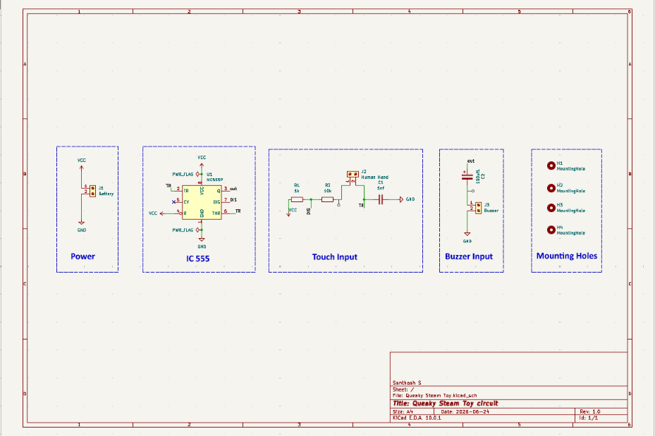
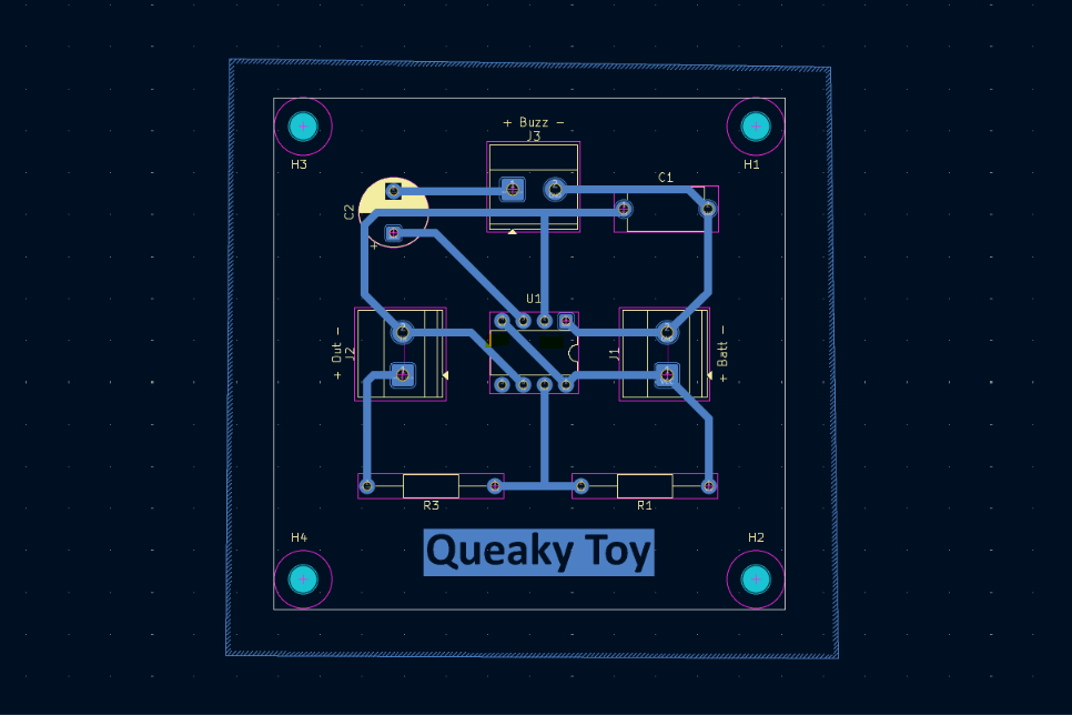
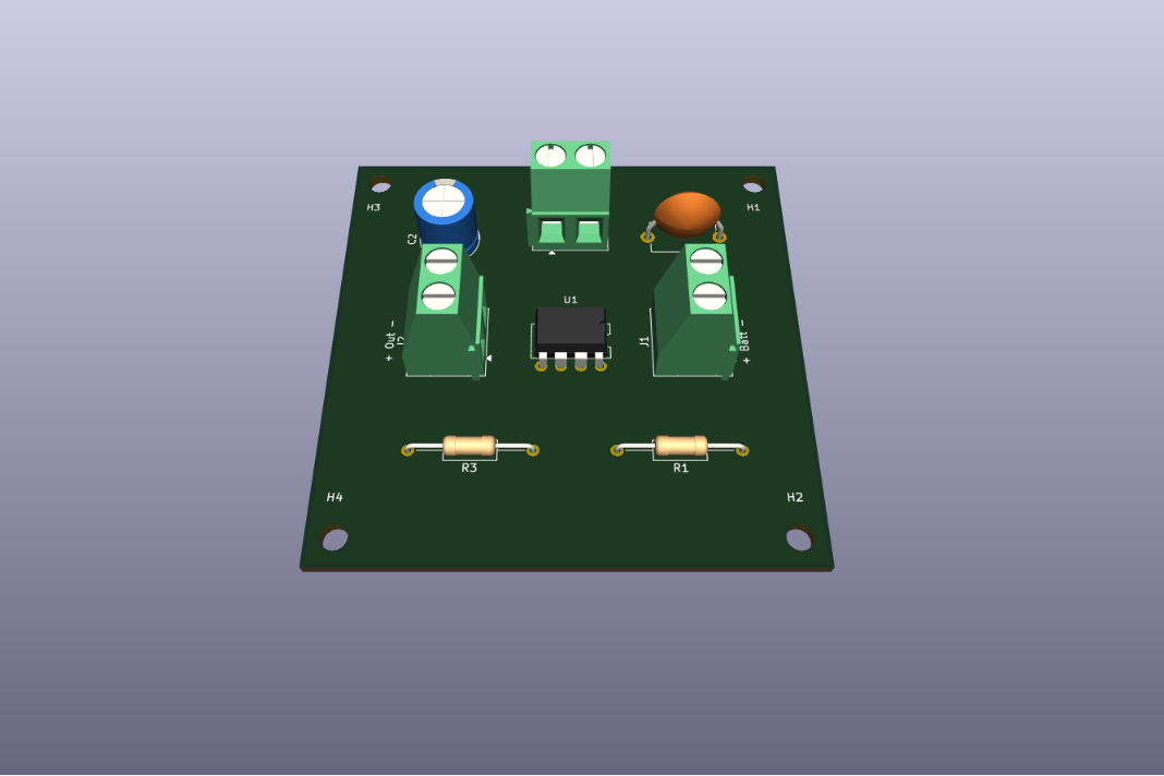
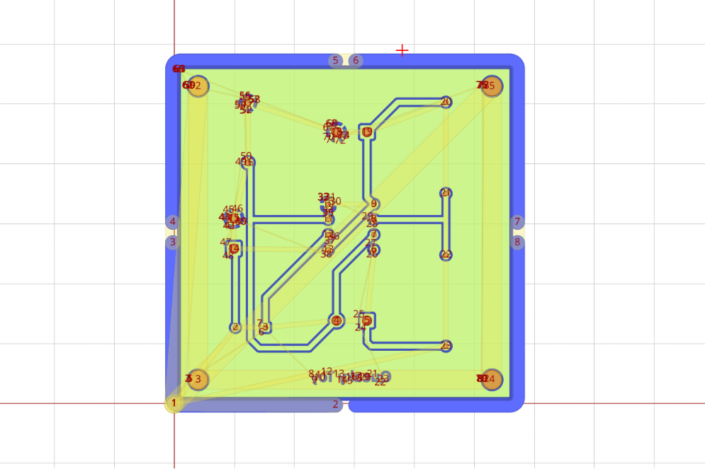
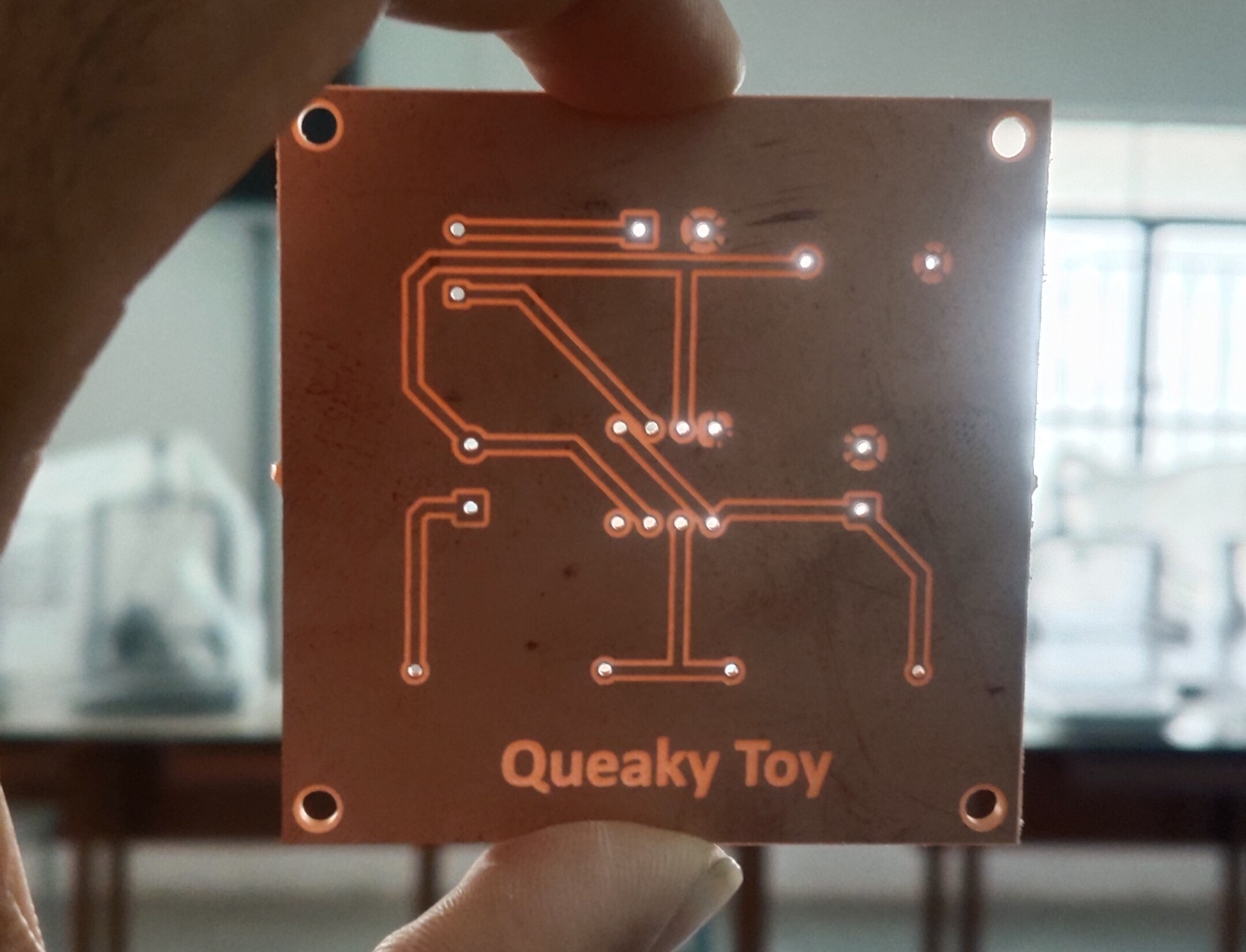
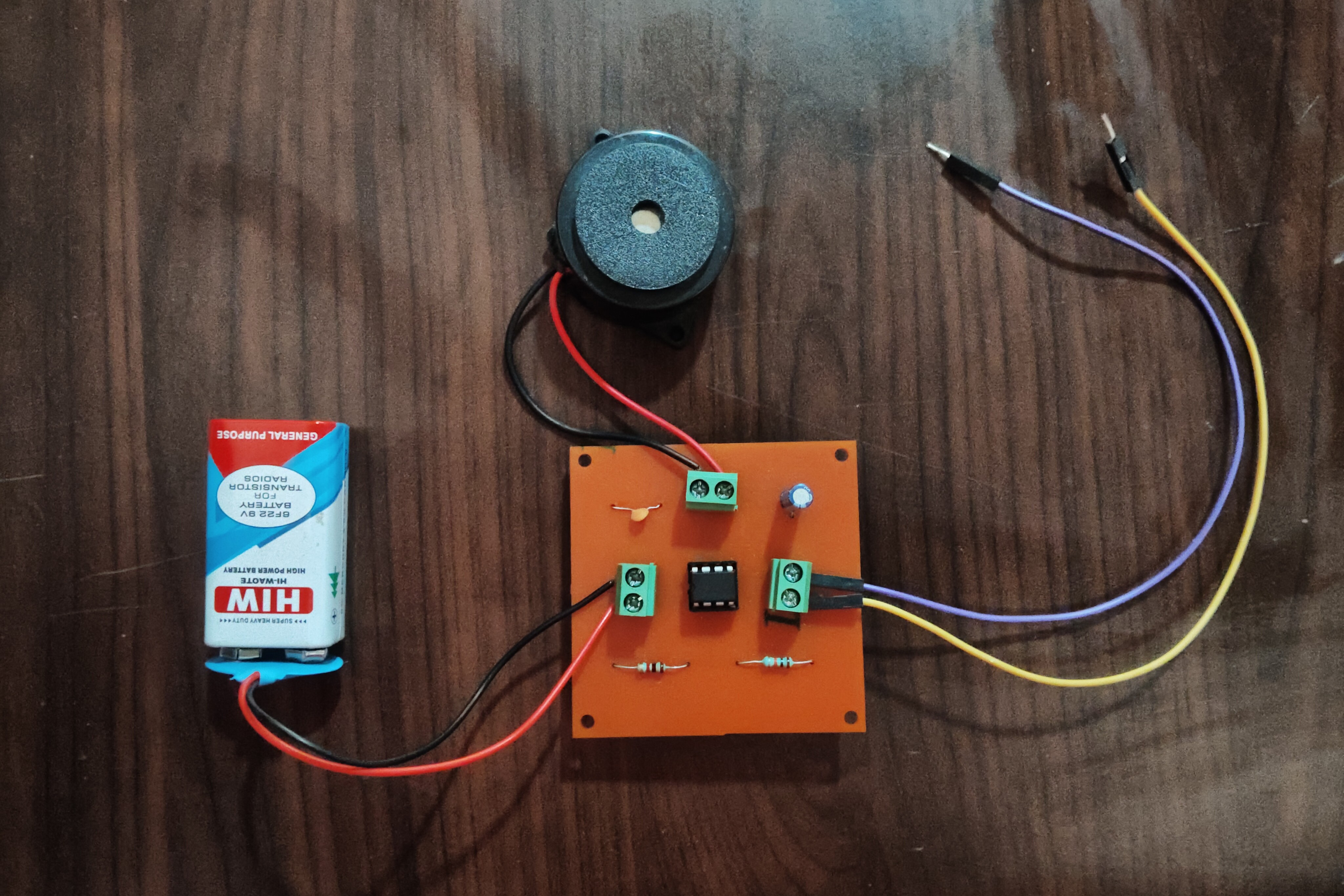
The touch sensor provides a trigger signal to the 555 Timer IC. Once triggered, the timer generates an output signal that drives the buzzer, producing a sound. The circuit is powered using a 9V battery.
Santhosh S
Electronics & PCB Design Enthusiast
KiCad | PCB Design | CNC PCB Fabrication | Embedded Systems
⭐ If you like this project, feel free to star the repository.
| Qty | Value | Footprint | References |
|---|---|---|---|
| 4 | MountingHole | MountingHole:MountingHole_3.2mm_M3 | H1, H2, H3, H4 |
| 1 | + Batt - | TerminalBlock_Phoenix:TerminalBlock_Phoenix_MKDS-1,5-2-5.08_1x02_P5.08mm_Horizontal | J1 |
| 1 | + Buzz - | TerminalBlock_Phoenix:TerminalBlock_Phoenix_MKDS-1,5-2-5.08_1x02_P5.08mm_Horizontal | J3 |
| 1 | + Out - | TerminalBlock_Phoenix:TerminalBlock_Phoenix_MKDS-1,5-2-5.08_1x02_P5.08mm_Horizontal | J2 |
| 1 | 100uf1 | Capacitor_THT:CP_Radial_D8.0mm_P5.00mm | C2 |
| 1 | 10k | Resistor_THT:R_Axial_DIN0207_L6.3mm_D2.5mm_P15.24mm_Horizontal | R3 |
| 1 | 1k | Resistor_THT:R_Axial_DIN0207_L6.3mm_D2.5mm_P15.24mm_Horizontal | R1 |
| 1 | 1nf | Capacitor_THT:C_Disc_D9.0mm_W5.0mm_P10.00mm | C1 |
| 1 | NE555P | Package_DIP:DIP-8_W7.62mm | U1 |
harinivas-b/STEM-TOY-USING-KICAD
To design a STEM TOY using KiCad by applying the basic concepts of PCB design

tomasondro/High-Voltage-Power-Supply
KiCad scheme for High Voltage Power Supply


barisdinc/N3B_SDR_Transceiver_HW
V/U/SHF and QO-100 SDR Transceiver Project

terjeio/PCBLaserMkII
Mechanical and electrical design files for revised version of my PCB Laser exposer


skumlos/if-c01comg-clone-tht-full
A full sized SCART/BNC version of the IF-C01COMG clone base board
It measures 61 × 61 mm and has 2 copper layers, 1.6 mm thick.
12 parts, built around the NE555P and 100UF/16V. The full list of its parts is on this page, with links to each part's symbol and footprint where PCBKit's library has them.
From the Santhosh7105/Queaky-Toy-PCB repository on GitHub, at the commit this page was made from: the board is PCB/Queaky Steam Toy.kicad_pcb and its schematic PCB/Queaky Steam Toy.kicad_sch. PCBKit opens the board in the browser, with nothing to install.
Its repository states no licence, so its author keeps all rights: ask Santhosh7105 before reusing the design.