2 layers52 × 29 mm
Cellular featherwing pcb
keenanjohnson/cellular-featherwing-pcb
The PCB Design for a Cellular Adafruit Featherwing based on the Quectel BG96 LTE Cat M1 & Cat NB1.
64 parts1

 Rocketdude1984/MMIN-Converter
Simple converter for mm to inches and inches to mm. Meant as a project to advance skills in PCB design and firmware development.
MINN Converter is an open-source printed circuit board by Rocketdude1984, from the Rocketdude1984/MMIN-Converter repository on GitHub. It is a 2-layer board of 63 × 104.5 mm with 66 parts on 60 nets, routed with 463 tracks and 78 vias.
It is built around the TPS61040DBV, TPS63020QDSJTQ1 and MBR0530, with the MK-12C02-G020 among its other parts. Its parts include 21 switches, 12 capacitors, 9 resistors, 3 ICs and 2 diodes. It belongs with the STM32 and NXP (LPC, Kinetis, i.MX RT) boards of this library.


Simple converter for mm to inches and inches to mm. Meant as a project to advance skills in PCB design and firmware development.
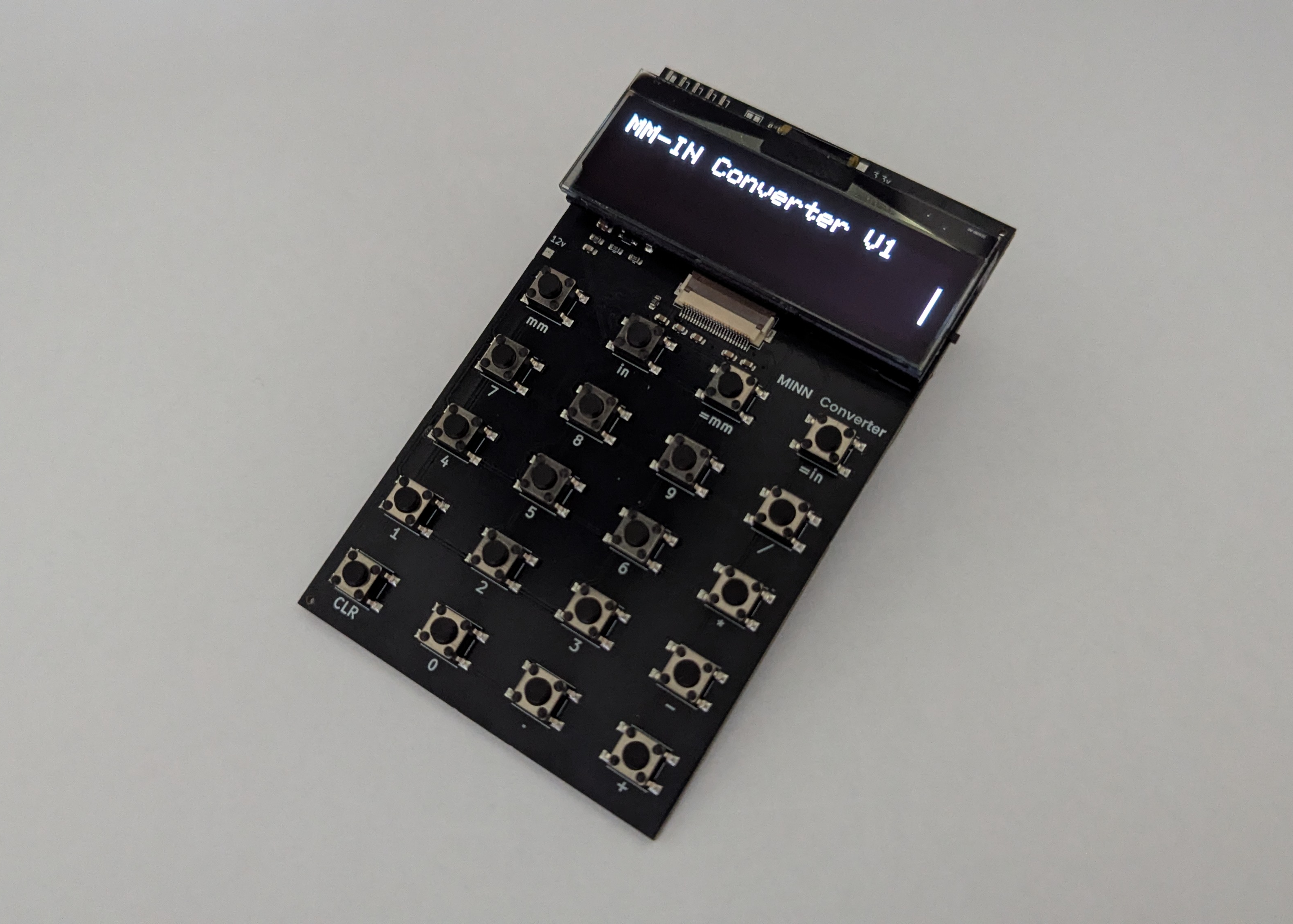
2xAA batteries
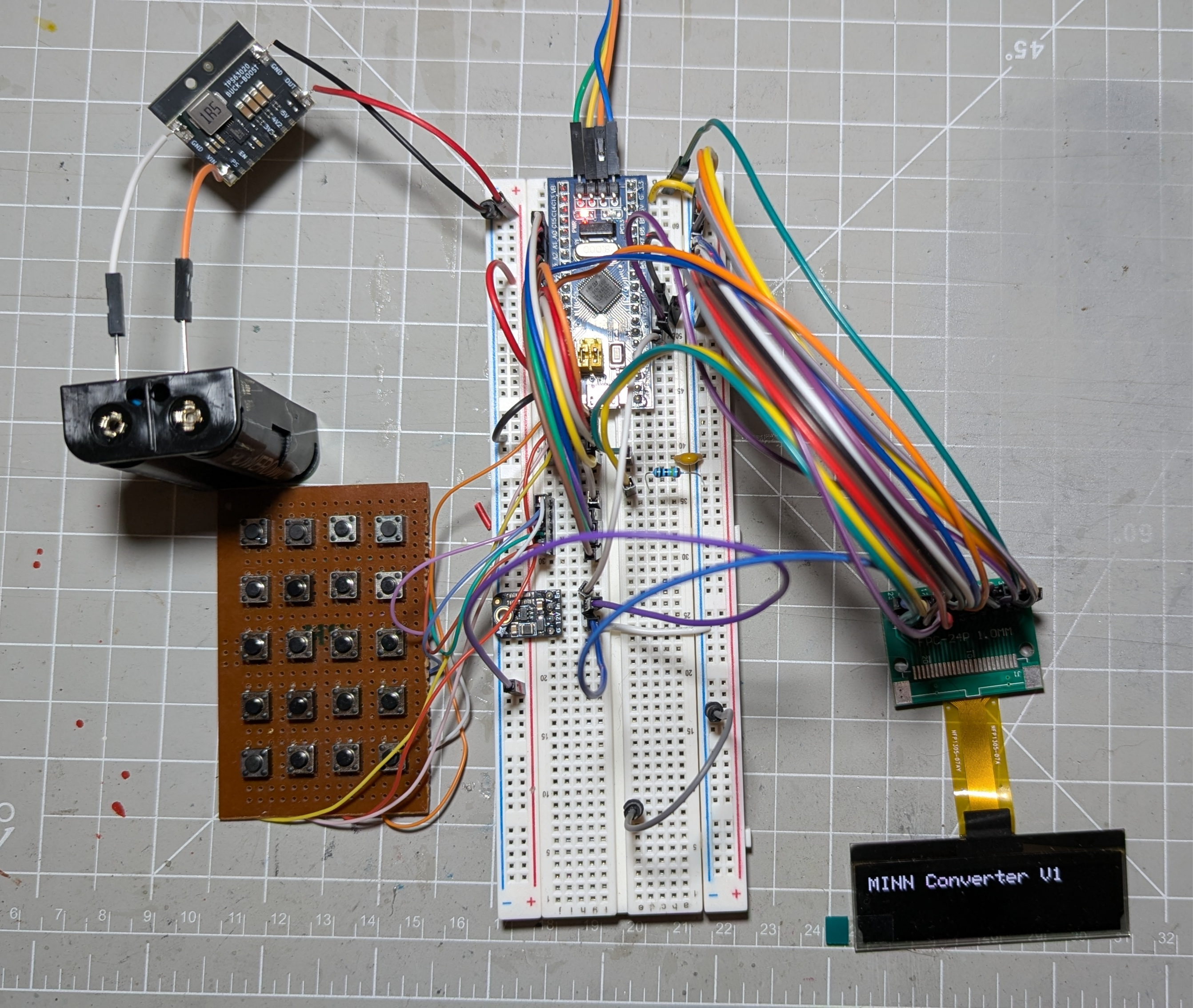
Production took a while longer than expected, but the project is complete.
After correcting a few lines of code the converter works great.
I made a few changes to the PCB based on what I learned from this first model. Mainly I forgot to put the pin designations for the serial connections on the silkscreen. And having an "ON/OFF" indication would have been nice. I tried to implement that in a new version of the board, but it is still not great because screen and battery comepletely cover each side of the switch.
| Qty | Value | Footprint | References |
|---|---|---|---|
| 20 | SW_Push | Button_Switch_SMD:SW_Push_1P1T_NO_6x6mm_H9.5mm | SW1, SW2, SW3, SW4, SW5, SW10, SW11, SW12, SW13, SW14, SW15, SW16, SW17, SW18, SW19, SW20 +4 |
| 4 | 100nF | Capacitor_SMD:C_0603_1608Metric | C3, C4, C12, C15 |
| 4 | 1µF | Capacitor_SMD:C_0603_1608Metric | C_COMH1, C6, C13, C14 |
| 4 | 22µF | Capacitor_SMD:C_0805_2012Metric | C_OUT_1, C_OUT_2, C_OUT_3, C17 |
| 3 | 100nf | Capacitor_SMD:C_0603_1608Metric | C8, C9, C10 |
| 2 | 100kΩ | Resistor_SMD:R_0603_1608Metric | R2, R9 |
| 2 | 10kΩ | Resistor_SMD:R_0603_1608Metric | R5, R6 |
| 2 | 10nF | Capacitor_SMD:C_0603_1608Metric | C5, C11 |
| 2 | 10µF | Capacitor_SMD:C_0805_2012Metric | C_IN_1, C_IN_2 |
| 2 | 1MΩ | Resistor_SMD:R_0603_1608Metric | R3, R8 |
| 1 | +12V | TestPoint:TestPoint_Pad_1.5x1.5mm | 12v |
| 1 | +3.3V | TestPoint:TestPoint_Pad_1.5x1.5mm | 3.3v |
| 1 | 180kΩ | Resistor_SMD:R_0603_1608Metric | R4 |
| 1 | 1µH, 57mΩ | Inductor_SMD:L_Murata_DFE201610P | L2 |
| 1 | 3.3pF | Capacitor_SMD:C_0603_1608Metric | C_FF1 |
| 1 | 3.3µH | Inductor_SMD:L_1008_2520Metric | L1 |
| 1 | 330 | Resistor_SMD:R_0603_1608Metric | R7 |
| 1 | 4.7µF | Capacitor_SMD:C_0805_2012Metric | C2 |
| 1 | 4.7µF | Capacitor_SMD:C_0603_1608Metric | C7 |
| 1 | 4µF | Capacitor_SMD:C_0805_2012Metric | C1 |
| 1 | 875kΩ | Resistor_SMD:R_0603_1608Metric | R1 |
| 1 | LED | LED_SMD:LED_0603_1608Metric | D2 |
| 1 | MBR0530 | Diode_SMD:D_SOD-123 | D1 |
| 1 | MK-12C02-G020 | MK12C02:MK-12C02-G020_GSW | SW21 |
| 1 | OLED CONN | Connector_FFC-FPC:Hirose_FH12-24S-0.5SH_1x24-1MP_P0.50mm_Horizontal | J2 |
| 1 | SERIAL DEBUG | Connector_PinHeader_2.54mm:PinHeader_1x05_P2.54mm_Horizontal | J1 |
| 1 | STM32F103C8Tx | Package_QFP:LQFP-48_7x7mm_P0.5mm | U3 |
| 1 | SolderJumper_2_Open | Jumper:SolderJumper-2_P1.3mm_Open_Pad1.0x1.5mm | BOOT |
| 1 | TPS61040DBV | Package_TO_SOT_SMD:SOT-23-5 | U1 |
| 1 | TPS63020QDSJTQ1 | TPS63020:DSJ14_2P85X1P58_TEX | U2 |
The 65 most common of 66 parts.
keenanjohnson/cellular-featherwing-pcb
The PCB Design for a Cellular Adafruit Featherwing based on the Quectel BG96 LTE Cat M1 & Cat NB1.

TalismanDesign/PocketMage_PDA
An E-Ink PDA device using the ESP32 S3.


betz-engineering/ui_board_1u
User interface PCB for 1U chassis front-panels

Novin3dp/7inch-hdmi-screen
این برد دولایه (۶۸×۴۲ میلیمتر) همان پنل ۷ اینچ AT070TN92 و تاچ GT915 را این بار از پورت DSI رزبریپای راه میاندازد. نسخهی HDMI در پوشهی hardware/ دستنخورده باقی مانده است.

aidanaalund/sleep-wearable
Work on our sleep state tracker wearable headband for ECE Senior Design at UT Austin. Members are Aidan Aalund, Justin Banh, Alex Ho, and Kien Ton. Mentored by Dr. Edison Thomaz.

SpacehuhnTech/USB-Nova-MkII-PCB
USB Nova is a cute little USB “drive” that acts as a keyboard, much like the USB Rubber Ducky, WiFi Duck, and other BadUSBs.

It measures 63 × 104.5 mm and has 2 copper layers, 1.6 mm thick.
66 parts, built around the TPS61040DBV, TPS63020QDSJTQ1, MBR0530 and MK-12C02-G020. The full list of its parts is on this page, with links to each part's symbol and footprint where PCBKit's library has them.
From the Rocketdude1984/MMIN-Converter repository on GitHub, at the commit this page was made from: the board is Kicad/MINN-Converter.kicad_pcb and its schematic Kicad/MINN-Converter.kicad_sch. PCBKit opens the board in the browser, with nothing to install.
Its repository states no licence, so its author keeps all rights: ask Rocketdude1984 before reusing the design.