4 layers66 × 60 mm
MainFlightComputer
RockSat-X/RSXVT2026
Our experiment aims to evaluate the use of optical navigation with Commercial-off-the-Shelf (COTS) products for use in spaceflight applications.
72 parts3MIT
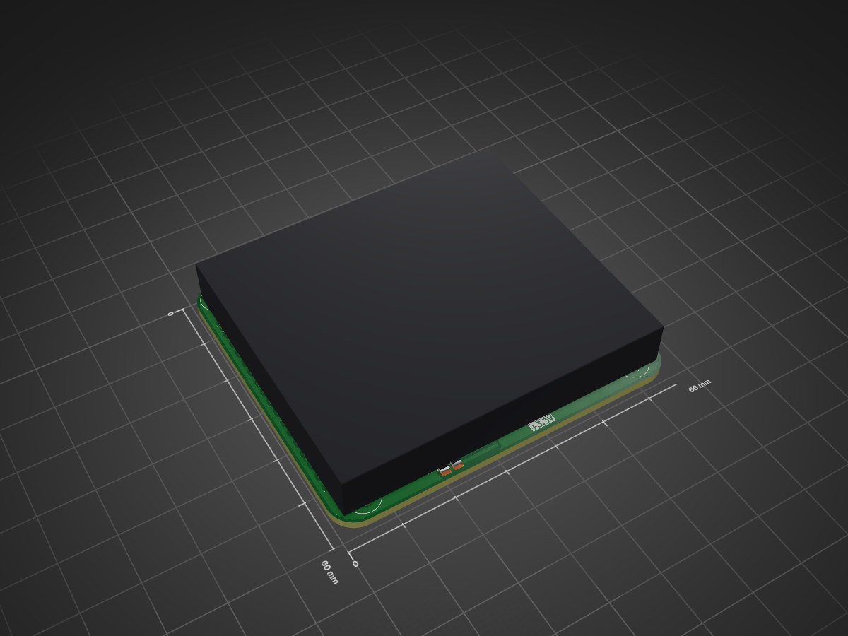
 RockSat-X/RSXVT20263
Our experiment aims to evaluate the use of optical navigation with Commercial-off-the-Shelf (COTS) products for use in spaceflight applications.
MainPowerDistributionSystem is an open-source printed circuit board by RockSat-X, from the RockSat-X/RSXVT2026 repository on GitHub, published under the MIT licence. It is a 2-layer board of 66 × 60 mm with 45 parts on 73 nets, routed with 79 tracks and 19 vias.
It is built around the BTS462TATMA1, LM339 and 1N4727A. Its parts include 15 resistors, 7 capacitors, 6 diodes, 5 ICs and 2 connectors.


[!IMPORTANT] Quick link to:
Also check out the RSXVT2026 Wiki!
Our experiment aims to evaluate the use of optical navigation with Commercial-off-the-Shelf (COTS) products for use in spaceflight applications. To conduct the experiment, an autonomous attitude determination and control system (ADCS) employing an optical navigation system (ONS) will be designed to control a 1U CubeSat, codenamed Commercial Optical Navigation Satellite (CONSat).
The 2024 NASA Civil Space Shortfall Ranking lists 9 out of the top 30 shortfalls as limitations with autonomous deep space navigation. With recent advancements in computing and ML capabilities, optical navigation could revolutionize deep space navigation. Our team aims to address some of the challenges facing the space industry by designing a cost-effective ADCS that would rely primarily on conditions only available in deep space.
The CONSat vehicle's Optical Navigation System (ONS) has:
The operating principle of the CONSat will be to:
The target will be the Earth's horizon as seen at ~190 km apogee.
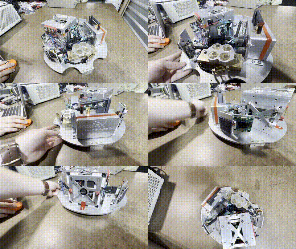
Deck-plate integrated experiment.
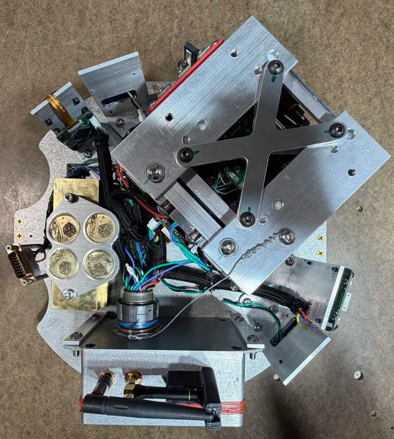
Top-down view of the deck-plate integrated experiment.
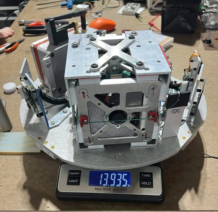
Weight of the deck-plate integrated experiment (13.935 pounds / 6.321 kilograms).
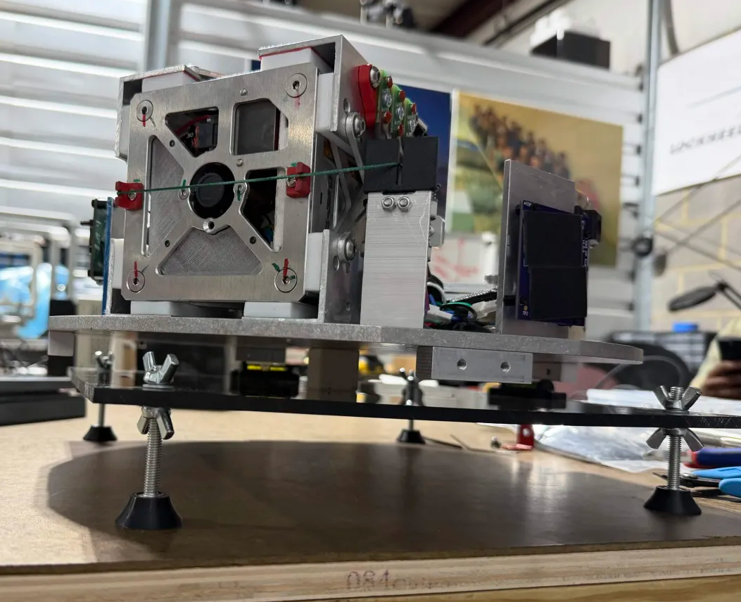
Center of gravity of the deck-plate integrated experiment.
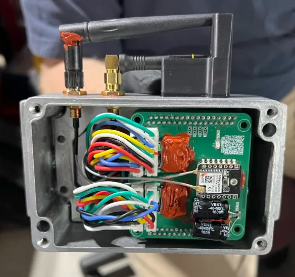
The inside of the main electronics box enclosure.
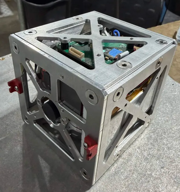
CONSat vehicle.
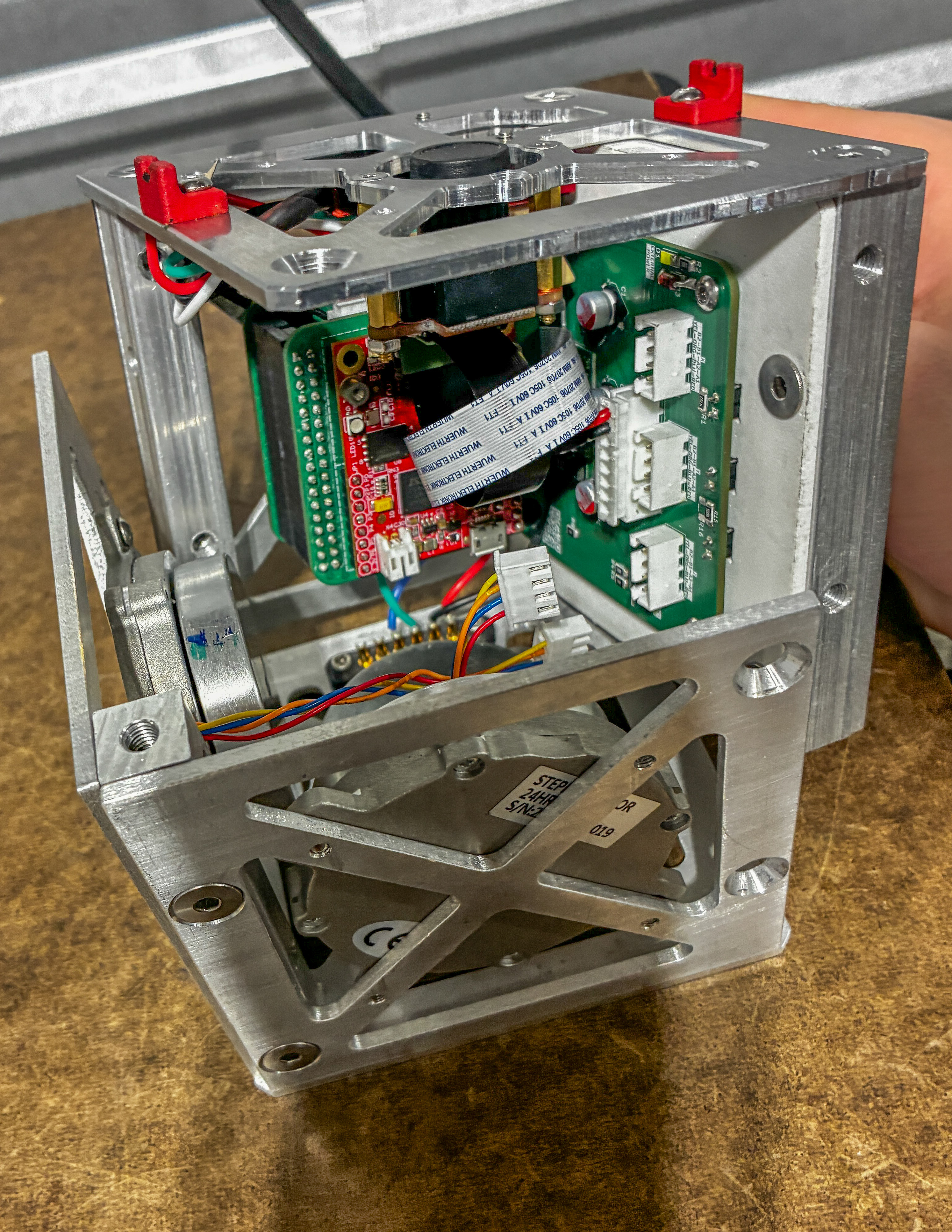
The inside of the CONSat vehicle.
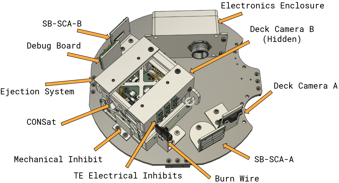
Labeled CAD model of the experiment.
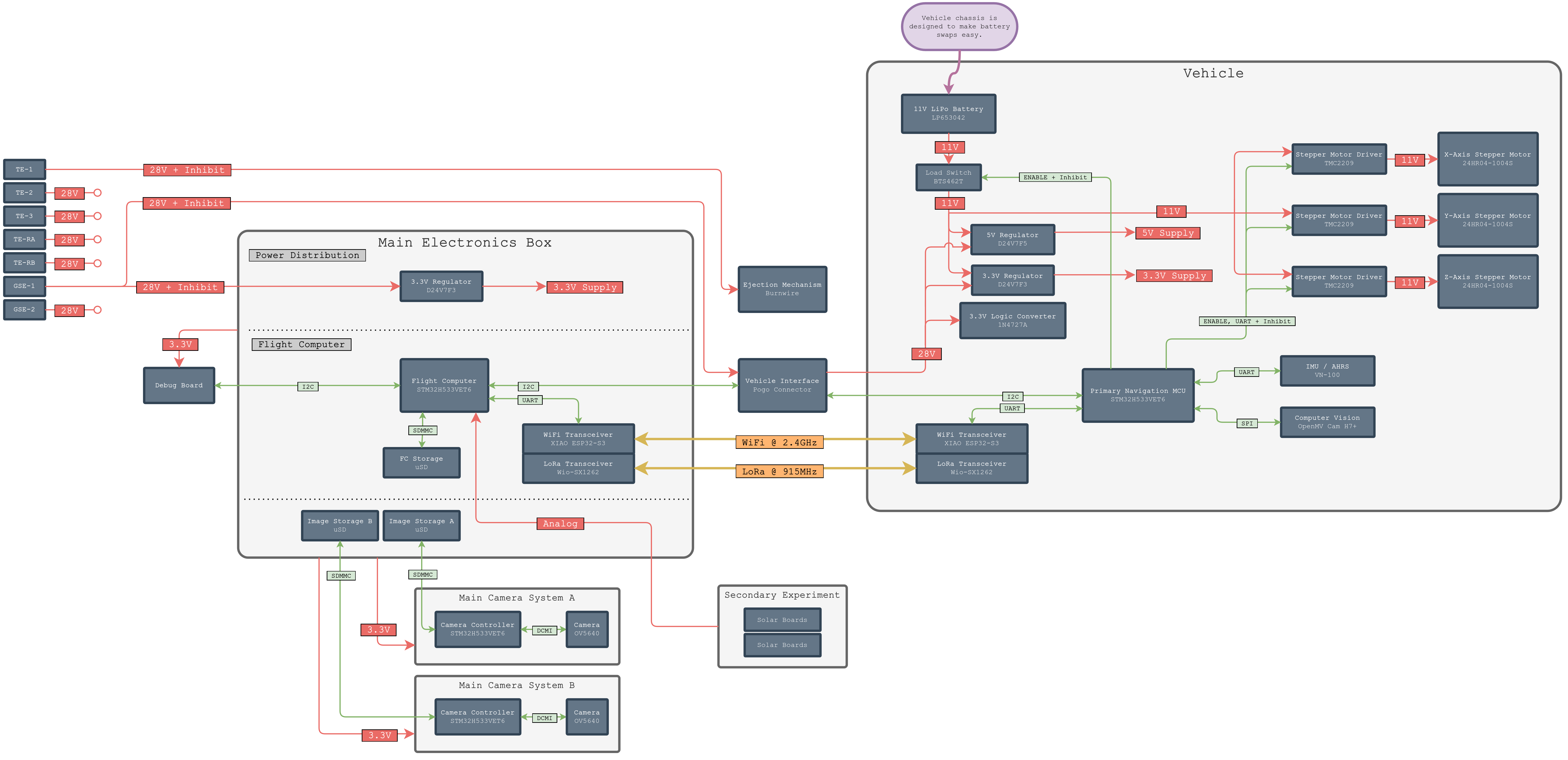
Functional block diagram of the CONSat experiment.
The experiment has two Main Camera Systems: one placed before the ejection mechnism and one next to a Solarboard by the burn-wire mechanism.
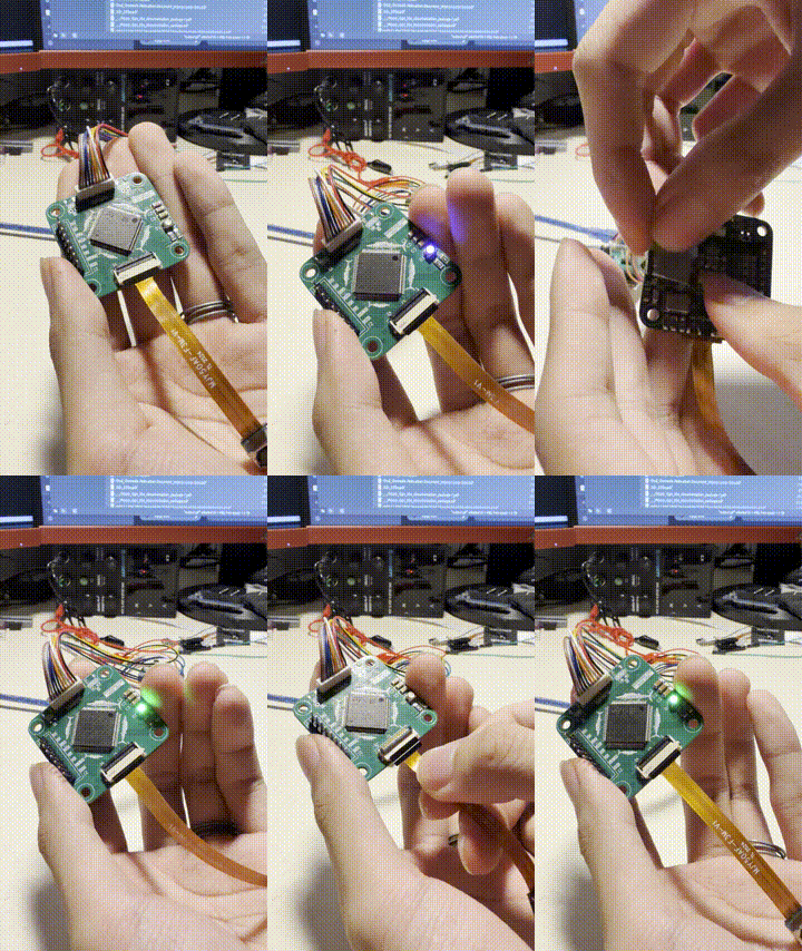
Main Camera System demonstration.
The Main Camera System board has a single RGB LED.
| Color | Description |
|---|---|
| White | Reformatting uSD card. |
| Magenta | Initializing uSD card. |
| Blue | Initializing OV5640 camera module. |
| Toggling green | Recording successfully. |
| Red | Main Camera System resetting. |
The Main Camera System creates a binary blob file for each recording.
Use cli.py parseVideo to convert the binary blob file into an MP4 video.
The Debug Board has a display to indicate the status of subsystems from the perspective of the Main Flight Computer. When the experiment is powered on via GSE-1, the Debug Board will initialize and play the Nokia buzzer tune. The display will also periodically invert color; this is just to indicate that the Debug Board MCU is still running.
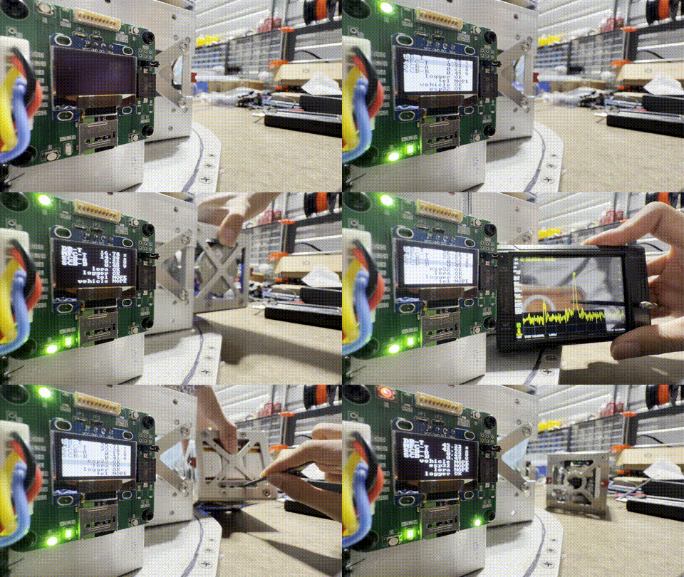
Debug board demonstration.
The Debug Board displays the following information.
| Field | Description |
|---|---|
DB-T | Time elapsed since the debug board was powered on. |
MFC-T | Time elapsed since the Main Flight Compiuter was powered on. |
SCB-A | Voltage of SB-SCA. |
SCB-B | Voltage of HP-SCA. |
te1 | Whether or not Main Flight Computer is detecting TE-1. |
vehicle | Whether or not Main Flight Computer is communicating with the Vehicle Flight Computer through the vehicle interface. |
esp32 | Whether or not Main Flight Computer is receiving ESP-NOW data packets. |
lora | Whether or not Main Flight Computer is receiving LoRa data packets. |
logger | Whether or not Main Flight Computer is saving data to its uSD card. |
If the Debug Board has not received the first debug packet from the Main Flight Computer yet,
then the field values will either be ??? or nan to indicate this.
[!IMPORTANT] A known issue with the Debug Board's display is that it is not resettable. That is, if the Debug Board MCU has a communication issue with the display driver, there's a small possibility that the display ends up in a corrupted state. This may appear as the screen being darker, the resolution looking off, or is completely blank. The MCU has no way to fix this, but power-cycling will resolve this rare issue if it ever happens.
The debug board has four RGB LEDs.
| Label | Position | Description |
|---|---|---|
A | Top Right | Flashes colors when the buzzer is being driven; this is just an extra indicator that's useful for when the buzzer is mute. |
B | Top Left | White when the Main Flight Computer hasn't sent the first debug packet to the Debug Board yet; red when there's a bad status to be aware of such as the Main Flight Computer not having received RF data in a while. |
C | Bottom Right | Toggles red when the Main Flight Computer hasn't sent a debug packet in a while; toggles green when a debug packet has been received. |
D | Bottom Left | White when the uSD card is being formatted; magenta when the Debug Board is failing to initialize the uSD card; toggles green periodically when data is successfully being logged to the uSD card. |
[!IMPORTANT] If the Debug Board encounters an irrecoverable error, it'll panic and indicate this by flashing all LEDs red. The Debug Board should eventually reset itself and continue on as normal.
The debug board plays the following buzzer tunes.
| Tune | Description |
|---|---|
| Nokia | Debug Board is initializing (e.g. just powered on from GSE-1). |
| Hazard | Debug Board hasn't received a debug packet from the Main Flight Computer in a while. |
| Up and Down | te1 is active (i.e. burn-wire is going). |
| Deep Beep | Main Flight Computer is reporting a bad status (e.g. haven't received RF data in a while) |
| Tetris | The Debug Board's uSD card is being reformatted. |
To mute the buzzer, leave the header above the buzzer open. To enable the buzzer, have a jumper shorting two adjacent pins; which pins are shorted determines the volume of the buzzer.
The uSD card is optional to the operation of the Debug Board. The Debug Board uses LED D to indicate that it's successfully saving log data.
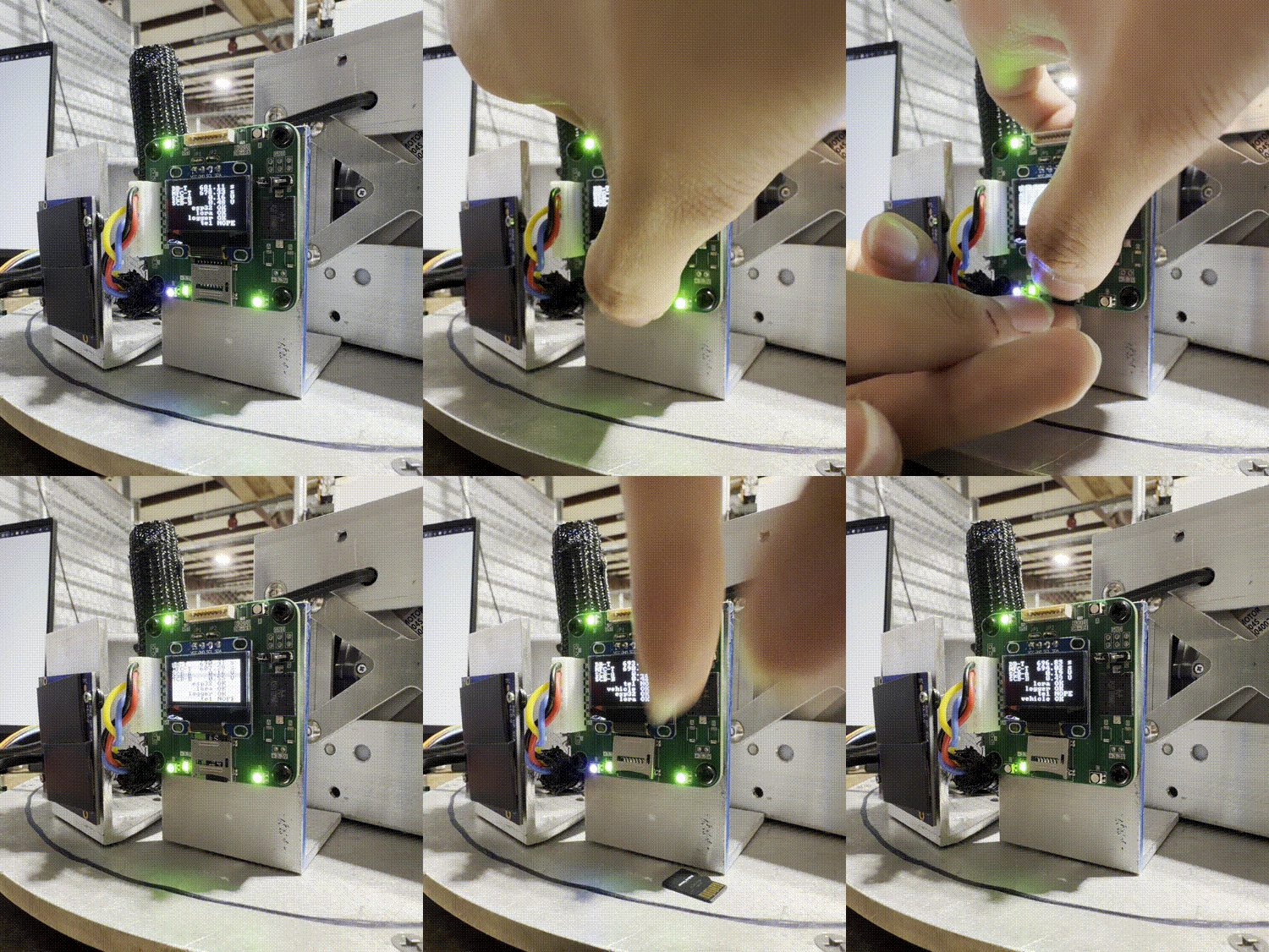
To load a uSD card, lift the connector lid up,
place the uSD card,
and slide the lid down to secure it.
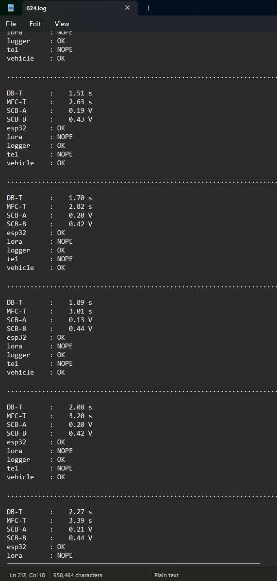
The Debug Board creates an ASCII text file with
the same information displayed on its screen.
The following table details the corresponding buzzer tune and RGB LED behavior for when a Vehicle Flight Computer diagnostic is reported.
| Severity | Tune | RGB LED | Description |
|---|---|---|---|
| :bangbang: | Ambulance | Fast toggling red | TMC2209 stepper motor drivers are failing initialization. This could be due to bad ribbon cable connection, dead batteries, inhibited batteries, or something else. |
| :warning: | Heartbeat | Slow toggling red | Vehicle Flight Computer has saturated a motor's RPM velocity. |
| :warning: | Tetris | Slow toggling white | Vehicle Flight Computer is reformatting the uSD card. |
| :warning: | Mario | Fast toggling white | Resetting the Vehicle ESP32 due to an issue with it. |
| :warning: | Three Tone | Fast toggling white | Resetting the Vehicle OpenMV due to an issue with it. |
| :bangbang: | Hazard | Fast toggling blue | Communication issue with VN-100. |
| :white_check_mark: | Nokia | Slow toggling white | Vehicle Flight Computer detecting that the vehicle has been redocked. |
| :white_check_mark: | Birthday | Slow toggling white | Vehicle Flight Computer detecting that the vehicle has been ejected. |
| :warning: | Heavy Beep | Toggling magenta | Initialization issue with uSD card. This is okay if no uSD card is loaded. |
| :white_check_mark: | Burp | Blue blink | VN-100 communication okay. |
| :white_check_mark: | Chirp | Green blink | uSD card logging okay. |
| :white_check_mark: | Waking Up | None | Vehicle Flight Computer initializing (i.e. on activation of GSE-1); vehicle batteries are enabled at end of buzzer tune. |
| :white_check_mark: | Star Wars | None | Vehicle Flight Computer performing a dock shutdown (i.e. about to turn vehicle batteries off and resetting). |
| Severity | Description |
|---|---|
| :bangbang: | Something is likely very problematic and should be addressed as soon as possible. |
| :warning: | A non-fatal or recoverable issue. |
| :white_check_mark: | Positive or expected indicator of a working system. |
The three pin header on the Vehicle Flight Computer can be left open to mute the buzzer, otherwise short a pair of adjacent pins to determine the volume of the buzzer.
The Vehicle Flight Computer board also has an optional uSD card slot for log data.
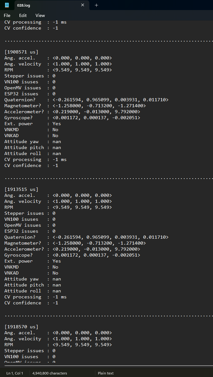
The Vehicle Flight Computer creates an ASCII text file with information
like VN-100 IMU data, CVT results, current motor velocities, and so on.
The OpenMV H7+ has a single RGB LED.
| RGB LED | Description |
|---|---|
| Flashing blue | The CVT algorithm hasn't detected the horizon yet. |
| Flashing green | The CVT algorithm has found the horizon. |
Each toggle of the RGB LED represents an entire image being captured, processed, and transmitted to the Vehicle Flight Computer. Because JPEG image compression is used, if the OpenMV H7+'s camera lens is covered (e.g. by a finger), the blinking of the RGB LED will be much faster.
If the OpenMV H7+'s RGB LED is not blinking, then it's very likely the program is not running, but the Vehicle Flight Computer should reset the OpenMV H7+ eventually after a time-out period.
No other colors or behavior should be expected from the RGB LED or the OpenMV H7+ module as a whole.
The Vehicle Power Distribution System has LED indicators to be aware of.
| LED | Description |
|---|---|
| Bright white | Vehicle interface providing power to the vehicle, thus this LED should be active if and only if the vehicle is docked and GSE-1 is active. |
| Yellow | Vehicle Flight Computer has enabled on-board battery power. The LED should be off when the Vehicle Flight Computer is initializing but should eventually turn on, unless the vehicle battery inhibit is in place, to which this LED will never turn on. |
The Vehicle Power Distribution System has three jumpers to be aware of.
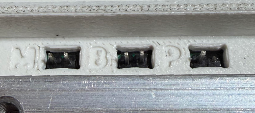
First jumper on the left denoted with "M" as in "Motor Inhibit".
Second jumper in the middle denoted with "B" as in "Battery Inhibit".
Third jumper on the right denoted with "P" as in "Power".
Note that the third "Power" jumper should only have its
first left pin and the second right pin is broken off.
| Jumper | Activation | Description |
|---|---|---|
| "M" | Use a shorting 2-pin jumper with pull tab. | Disable the control of the stepper motors. Vehicle Flight Computer can still initialize and operate, but reaction wheels will not spin. This is used to conserve battery charge, if needed. |
| "B" | Use a shorting 2-pin jumper with pull tab. | Disable the usage of the vehicle batteries. Vehicle Flight Computer can still initialize and operate via external power through the vehicle interface (i.e. GSE-1), but will immediately unpower upon being undocked. This can also be used to turn off the vehicle manually. |
| "P" | Use jumper wire to connect the pin to one of the vehicle batteries' positive terminal and wait several seconds. | Forces the usage of vehicle battery power, thus the Vehicle Flight Computer will initialize. This is to turn the vehicle on without relying on external power. |
[!TIP] A quick way to turn off the vehicle is by using an Allen key to short the middle "B" jumper.
During sequence testing and particularly GPS Roll-Out, it's critical to verify that RF systems are working as intended and to communicate this to NASA.
The easiest way to do this is to use the Debug Board. The screen will indicate if the Main Flight Computer is receiving RF data from the ESP32 and/or LoRa. If the Debug Board is loaded with a uSD card, the RF status will also be logged over time.
A more robust way to verify RF is to use the TinySA Spectrum Analyzer. There are two particular frequency bands of interest.
| Link | Center | Bandwidth | Start | End |
|---|---|---|---|---|
| ESP32 | 2.472 GHz | 20 MHz | 2.462 GHz | 2.482 GHz |
| LoRa | 920 MHz | 125 kHz | 919.9375 MHz | 920.0625 MHz |
Configure the spectrum analyzer to observe these frequencies.
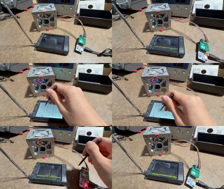
Spectrum analyzer demonstration.
You should see a reading similar the following figures:
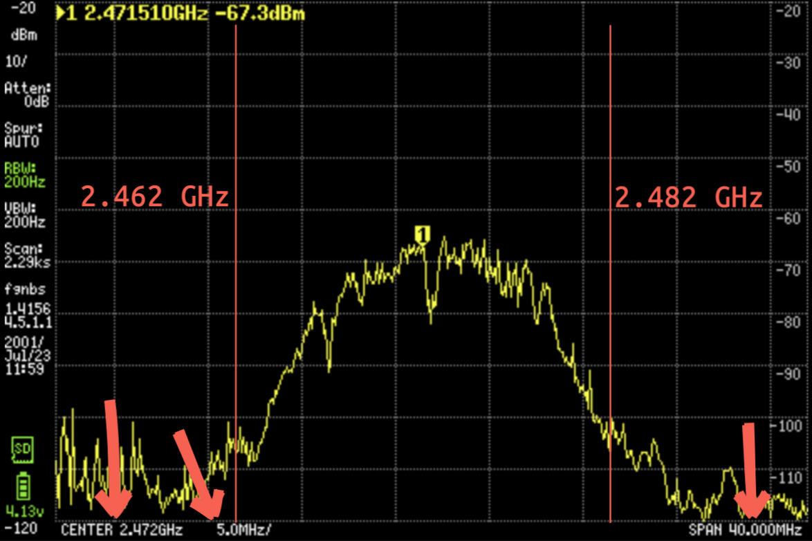
Spectrum analyzer measurement for the ESP32 link.
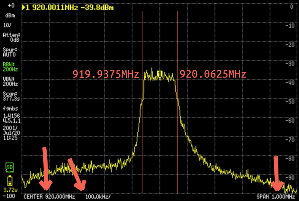
Spectrum analyzer measurement for the LoRa link.
[!IMPORTANT] The measurements shown in the figures were taken with an RBW value of 200 Hz; this makes the measurement more accurate but at the cost of being extremely slow. It's probably more productive to use an auto RBW value so measurements can be done quickly. Just as long there is an expected peak within frequency bands, all is good.
The RF verification process and expectations should be roughly as follows:
Before the experiment is powered on via GSE-1, no RF transmission is detected within the frequency bands.
Shortly after the experiment is powered on via GSE-1, ESP32 and LoRa transmission can be seen within the frequency bands.
RF transmission is sustained for at least the duration of a full mission; if applicable, the RF transmission should still be sustained even if the vehicle has ejected or becomes undocked.
RF transmission is sustained even when main has powered off (i.e. GSE-1 deactived) as the vehicle will continue transmitting via battery power.
RF transmission is no longer detected once the vehicle has powered off (either by using the vehicle battery inhibit or through a docked reset).
The following table summarizes the primary configurations needed to be set for tests done at Wallops.
| Expected Date | Test | Allow Ejection? | Enable TE-1? | Enable Main GSE-1? | Enable Vehicle GSE-1? |
|---|---|---|---|---|---|
| May 17th, 2026; Sunday | Pre-Flight Seq. | :white_check_mark: | :white_check_mark: | :white_check_mark: | :white_check_mark: |
| May 18th-19th, 2026; Monday-Tuesday | Pre-Vibe All-Fire Seq. | :white_check_mark: | :white_check_mark: | :white_check_mark: | :white_check_mark: |
| May 18th-19th, 2026; Monday-Tuesday | Pre-Vibe No-Fire Seq. | :x: | :x: | :white_check_mark: | :white_check_mark: |
| May 19th, 2026; Tuesday | Pre-Vibe Back Up Seq. | :x: | :x: | :white_check_mark: | :white_check_mark: |
| May 20th-21st, 2026; Wednesday-Thursday | Vibration Testing | :white_check_mark: | :white_check_mark: | :white_check_mark: | :white_check_mark: |
| May 22nd, 2026; Friday | Post-Vibe All-Fire Seq. | :white_check_mark: | :white_check_mark: | :white_check_mark: | :white_check_mark: |
| May 22nd, 2026; Friday | Post-Vibe No-Fire Seq. | :x: | :x: | :white_check_mark: | :white_check_mark: |
| May 22nd, 2026; Friday | Post-Vibe Back Up Seq. | :x: | :x: | :white_check_mark: | :white_check_mark: |
| May 22nd, 2026; Friday | GPS Roll-Out | :x: | :x: | :white_check_mark: | :white_check_mark: |
| June 19th, 2026; Friday | Final All-Fire Seq. | :white_check_mark: | :white_check_mark: | :white_check_mark: | :white_check_mark: |
| June 19th, 2026; Friday | Final No-Fire Seq. | :x: | :x: | :white_check_mark: | :white_check_mark: |
| June 19th, 2026; Friday | Final Back Up Seq. | :x: | :x: | :white_check_mark: | :white_check_mark: |
To allow ejection ( :white_check_mark: ), ensure the mechanical inhibit in front of the ejection mechanism is removed.
To prevent ejection ( :x: ), ensure the mechanical inhibit is secured in front of the ejection mechanism.
To have TE-1, Main GSE-1, or Vehicle GSE-1 be enabled ( :white_check_mark: ), insert a screw into the corresponding electrical screw switch on the side of the ejection mechanism. Verify short-circuit with a multimeter.
To have TE-1, Main GSE-1, or Vehicle GSE-1 be disabled ( :x: ), ensure a screw is not inserted into the corresponding electrical screw switch. Verify open-circuit with a multimeter.
[!IMPORTANT] The experiment must be put into flight-ready configuration during vibration testing. This means all electrical screw switches should be enabled and no mechanical inhibit present. Any loose components such as external uSD cards and jumpers should be removed (see RBF procedures). Screws should be applied with blue Loctite.
It should also be noted that Wallops will only provide GSE-1 and there will be no TE-1 power during this vibration test (this also applies to GPS Roll-Out).
[!IMPORTANT] The purpose of the electrical screw switches for Main GSE-1 and Vehicle GSE-1 is for flexibility. In the event that we need to ensure that the main avionics and/or vehicle does not power on, we have these as a way to do so.
The following steps are to be carried out in order with minimal deviations after all final sequence tests are done.
[!IMPORTANT] Pre-RBF procedure checklist:
- Multimeter.
- Three fully charged EEMB LP653042 3.7V 820mAh batteries.
- Allen key kit.
- Red Loctite.
- Tweezers.
- Needle-nose pliers.
- Phillips screwdriver.
Remove the ejection inhibit if still in place. The ejection inhibit will not be used again, so store it away in a secure location.
Take out the burn-wire mechanism in order to release the vehicle from the ejection mechanism. Place the burn-wire mechanism in a secure location.
Carefully undock vehicle and place it down on a table to be worked on.
Go to the side of the vehicle where the batteries are stored.
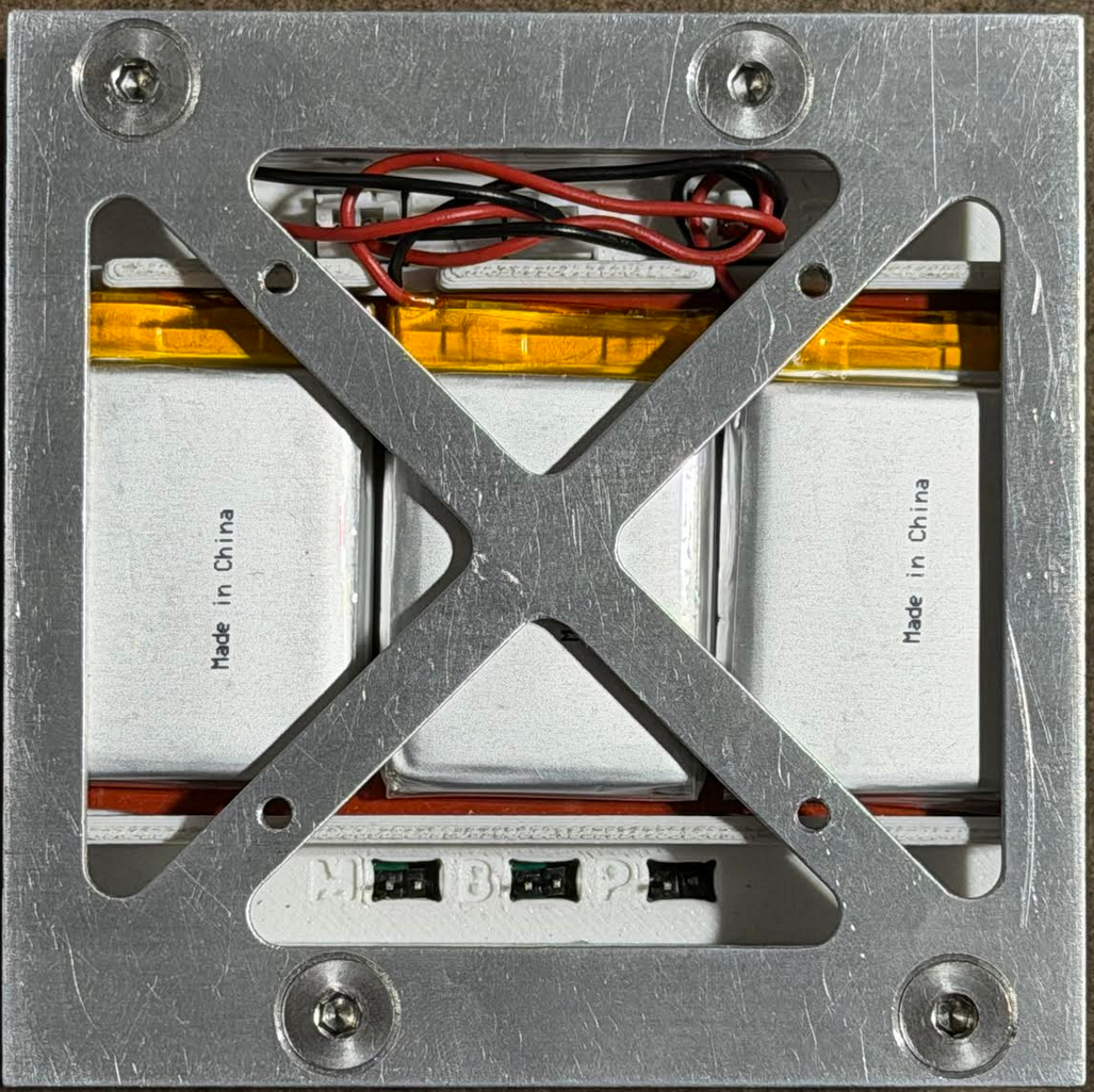
Side of the vehicle where the batteries are stored.
Take off the panel. Place the panel and screws in a secure location.
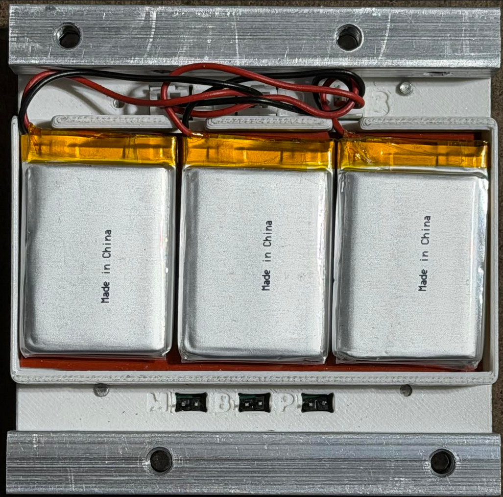
Panel that secured the vehicle's batteries removed.
Take out the old vehicle batteries. It is okay to tug on the cable to do so if excessive force is not used. Make sure to place the old vehicle batteries somewhere secure so it will not be confused with the new batteries.
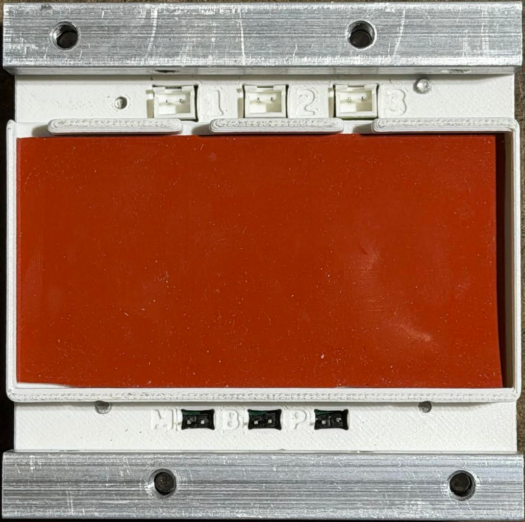
Vehicle batteries removed.
Verify that the new batteries (EEMB LP653042 3.7V 820mAh) are fully charged.
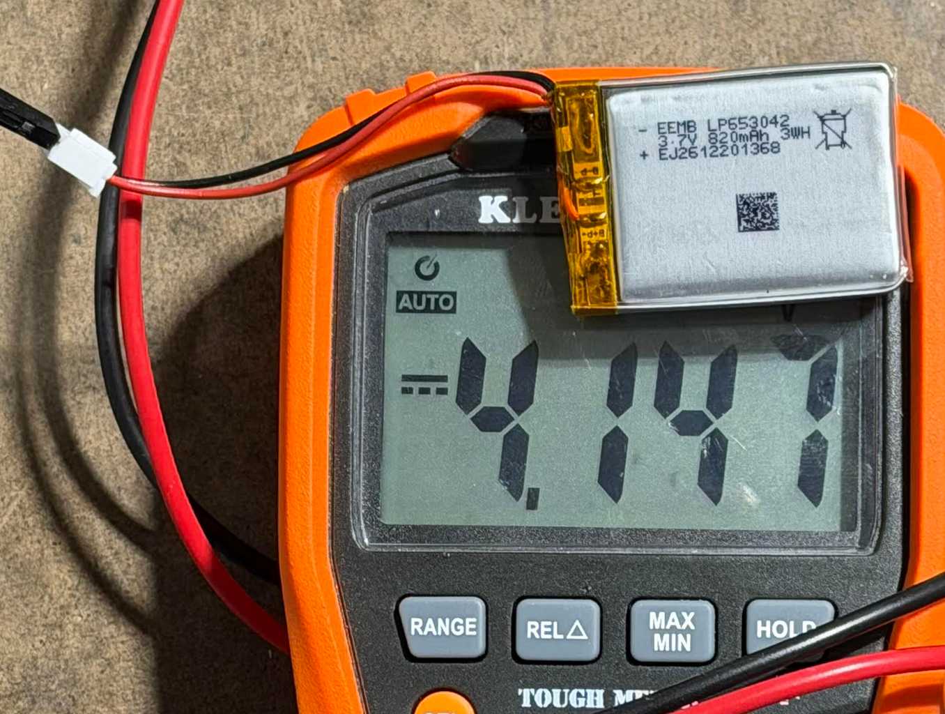
A fully charged vehicle battery should have at least 4V.
Verify that the new batteries have a JST-XH plug of the correct polarity.
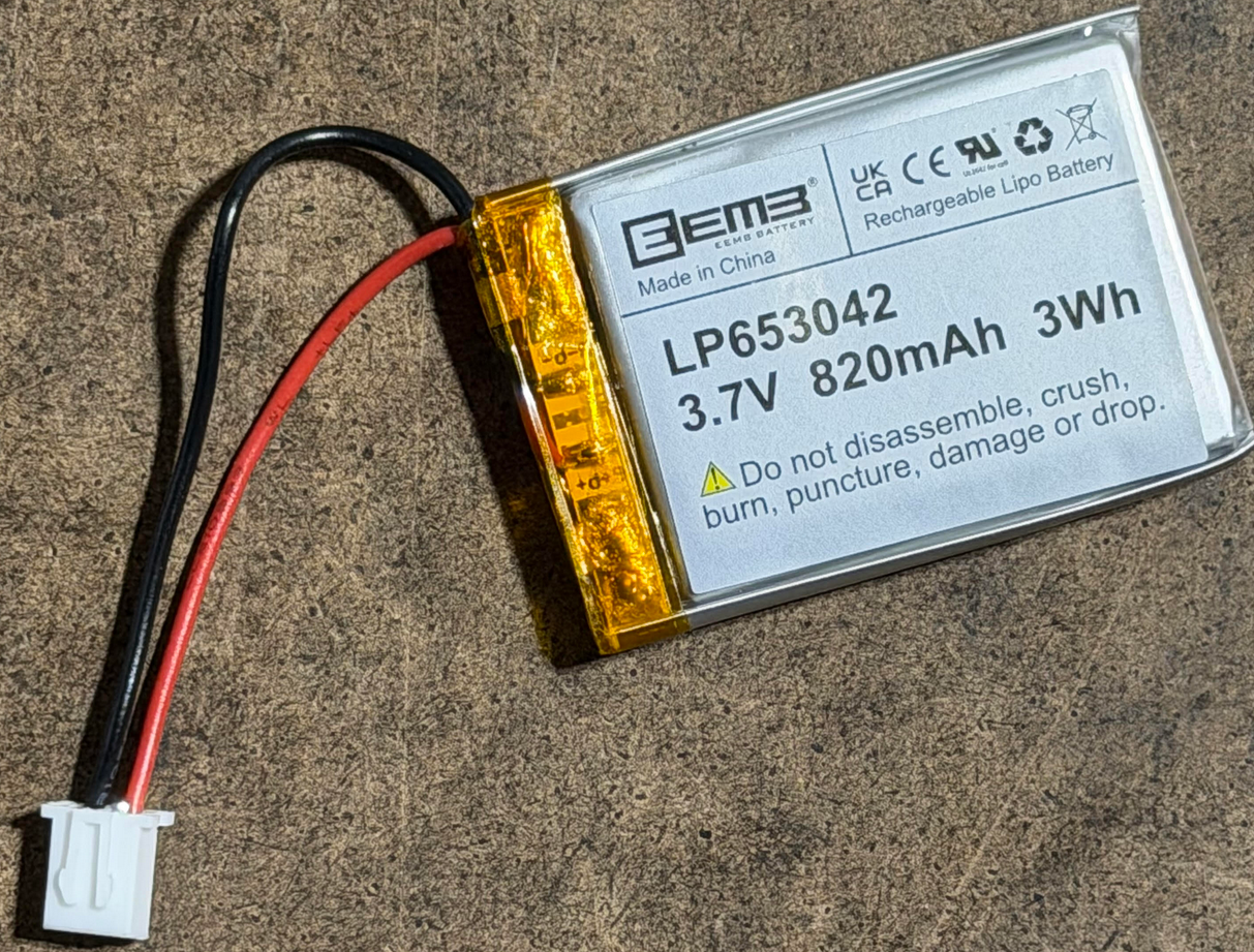
Note the plug polarity.
Put in the new vehicle batteries. The order in which the vehicle batteries are connected does not matter. Ensure the cables are well tucked to prevent them being crushed by the panel.
Vehicle batteries replaced.
Place and align the vehicle panel with the pillar's screw holes and verify that the battery cables will not be crushed.
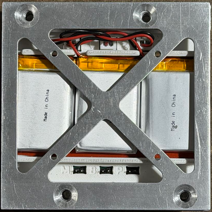
Vehicle panel aligned on top but not yet screwed.
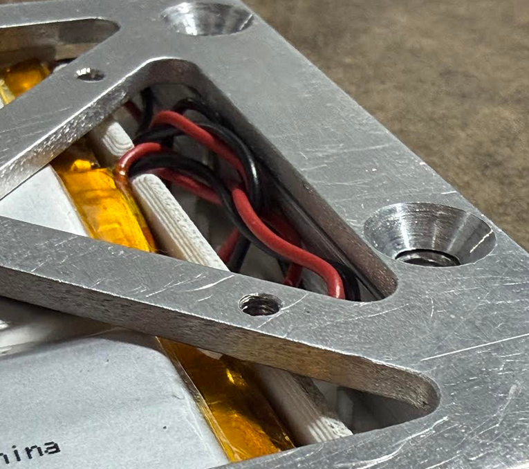
Battery cables tucked securely and not between the panel and pillar.
Apply red Loctite to the threads and reinsert screws to secure the panel.
Side of the vehicle where the batteries are stored.
Ensure the vehicle's jumpers for disabling motors, disabling batteries, and forcing vehicle power-on are all open-circuit as depicted below.
Vehicle jumpers in flight configuration.
Reinsert vehicle into the ejection mechanism. Make certain that the vehicle is in the correct orientation. Verify that the vehicle interface connectors are aligned.
Put the previously removed burn-wire mechanism back onto the deck-plate to secure the vehicle in the ejection mechanism. Apply red Loctite to screws during this process.
Visually verify and test that the vehicle is well secured by the ejection mechanism and burn-wire rope.
To prevent vibration risks, the Vehicle Flight Computer and Debug Board should have the lid of their uSD connectors be taken off. The pin header for the buzzer should also be left as an open circuit.
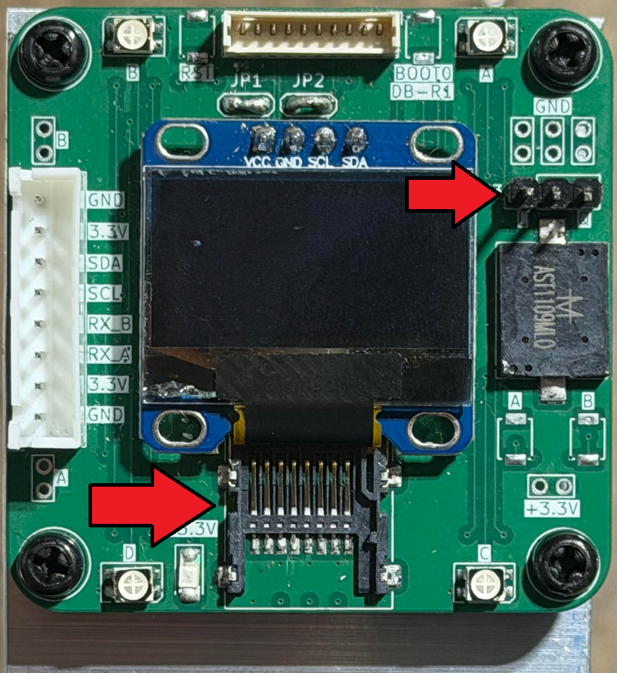
Debug Board without uSD card connector lid and buzzer jumper.
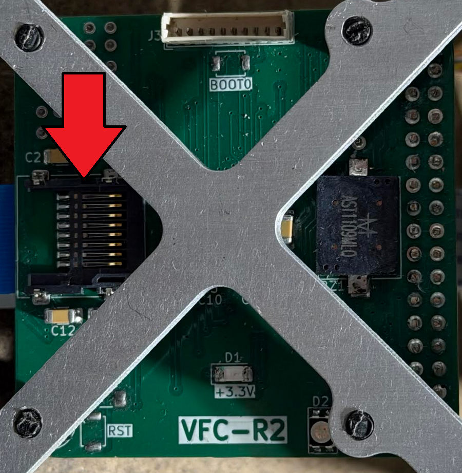
Vehicle Flight Computer without uSD card connector lid.
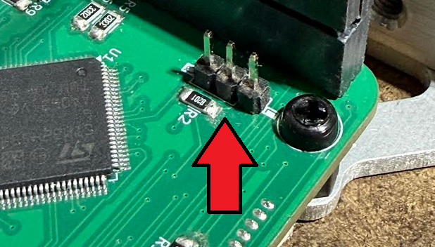
Vehicle Flight Computer without buzzer jumper.
Tweezers might be needed.
Insert screws with red Loctite into the three electrical screw switches on the side of the ejection mechanism.
Verify connectivity of each electrical screw switch by testing continuity of the two pads.
[!IMPORTANT] Verify that the following has been done:
- New vehicle batteries has been put in.
- Red Loctite has been applied to the vehicle's panel on the battery side.
- Red Loctite has been applied to the burn-wire mechanism.
- Red Loctite has been applied to the electrical screw switches.
- Vehicle is well secured by the burn-wire rope and ejection mechanism as a whole.
- No loose components like uSD card connector lids or jumpers are in place.
- Electrical screw switches have the expected connectivity.
These instructions describe how to fabricate the burnwire restraint lines using 1 mm braided line and two overhand loop knots.
The finished burnwire line should have:
Required materials:
Use an Overhand Loop Knot for both ends (video tutorial).

Overhand loop knot reference diagram.
Tie an overhand loop knot at the end of the line. Target loop length of approximately 1 inch. Leave a short tail after tightening the knot.
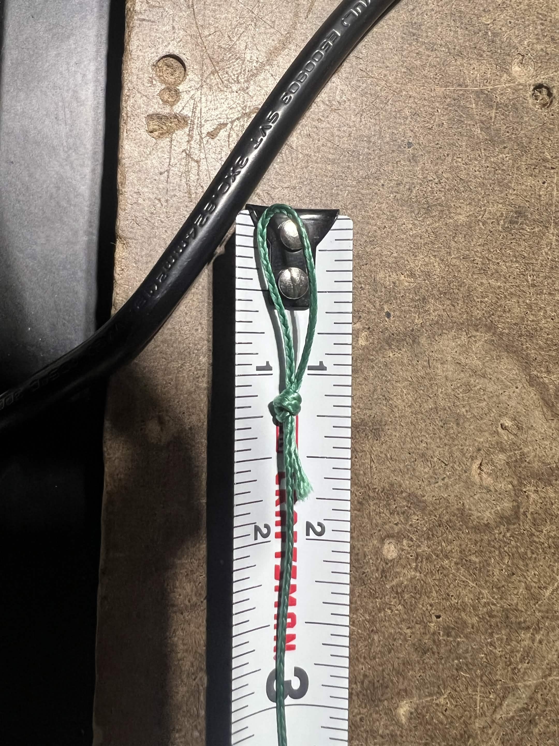
1 inch loop.
Using the tape measure, measure 13.5 inches from the tip of the loop. Mark this location with a marker.
[!IMPORTANT] Do NOT cut the line yet.
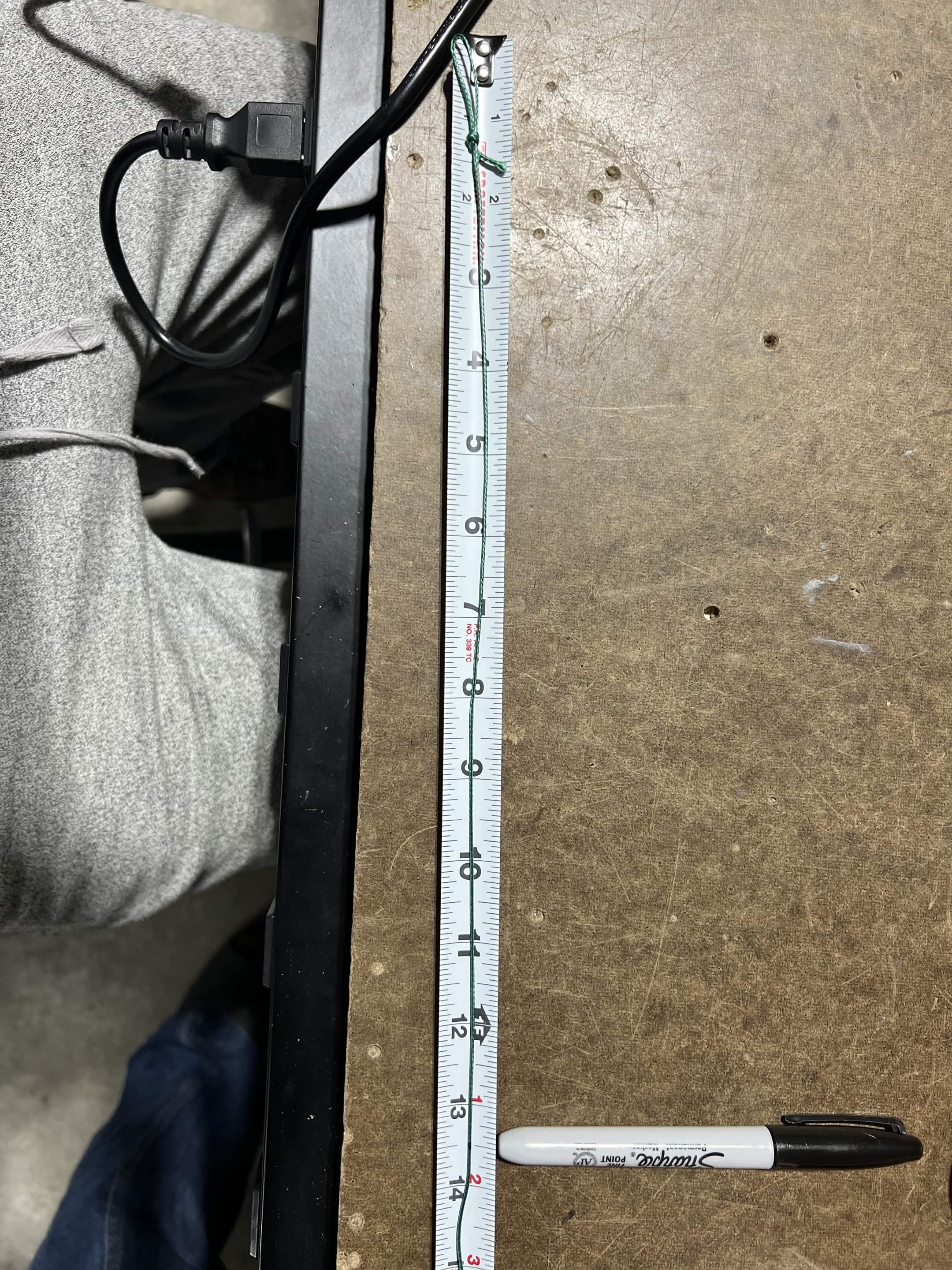
13.5 inch mark.
Fold the line in half at the 13.5 inch mark. Ensure the marked location becomes the tip of the second loop.
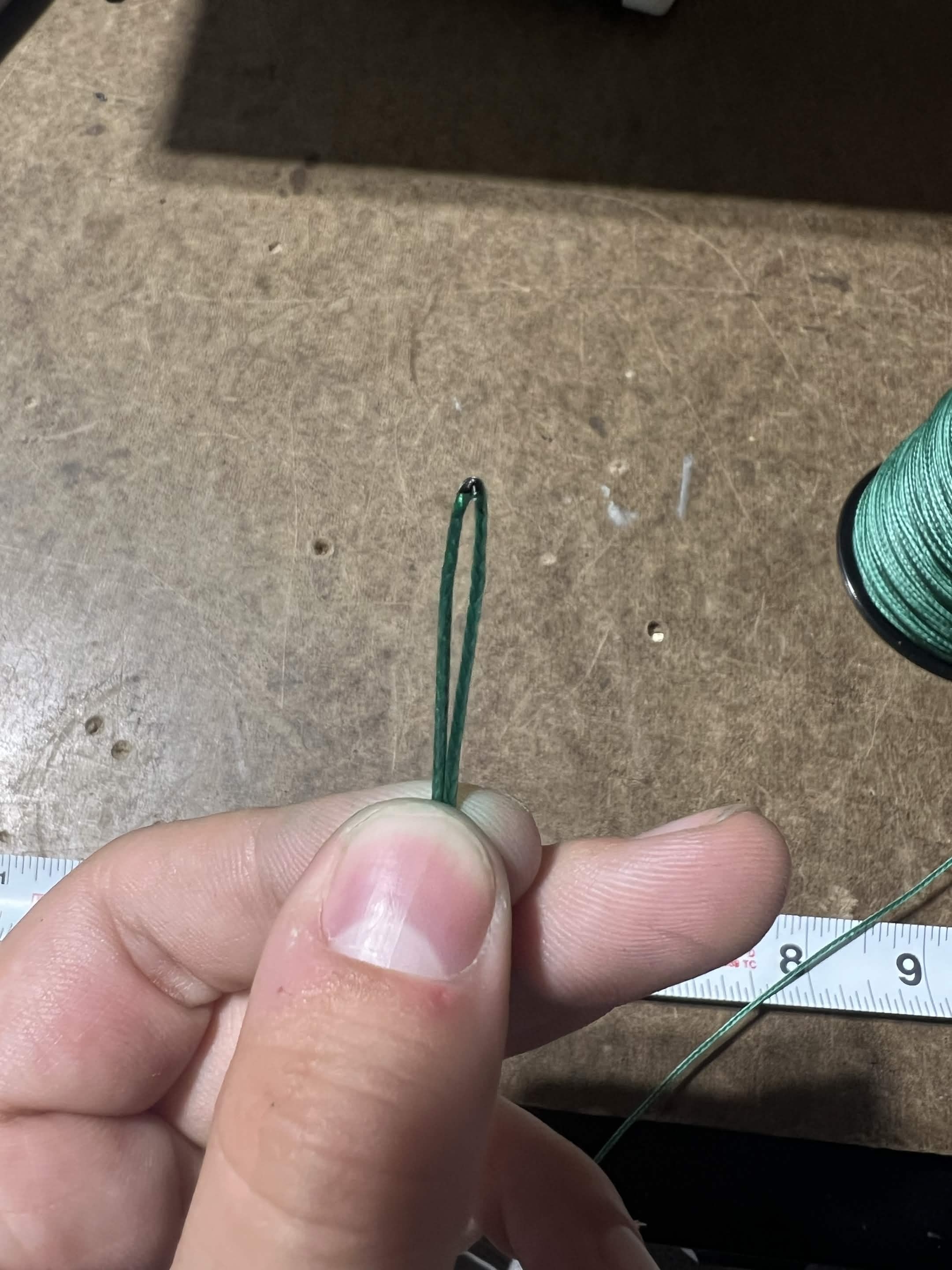
Folded at mark.
Tie another overhand loop knot. Loop length should again be approximately 1 inch. Ensure the black mark is positioned at the tip of the loop before tightening.
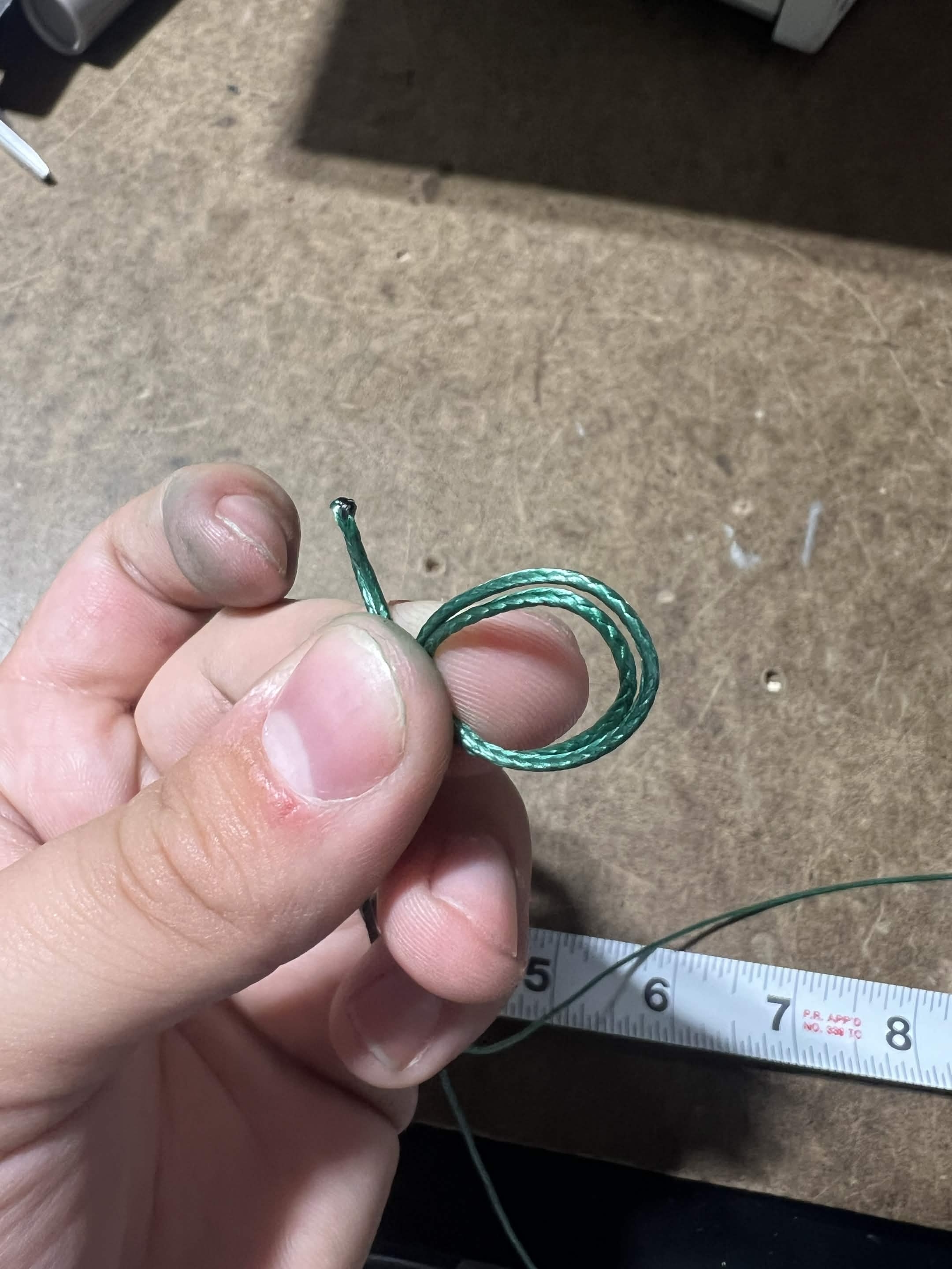
End loop first step.
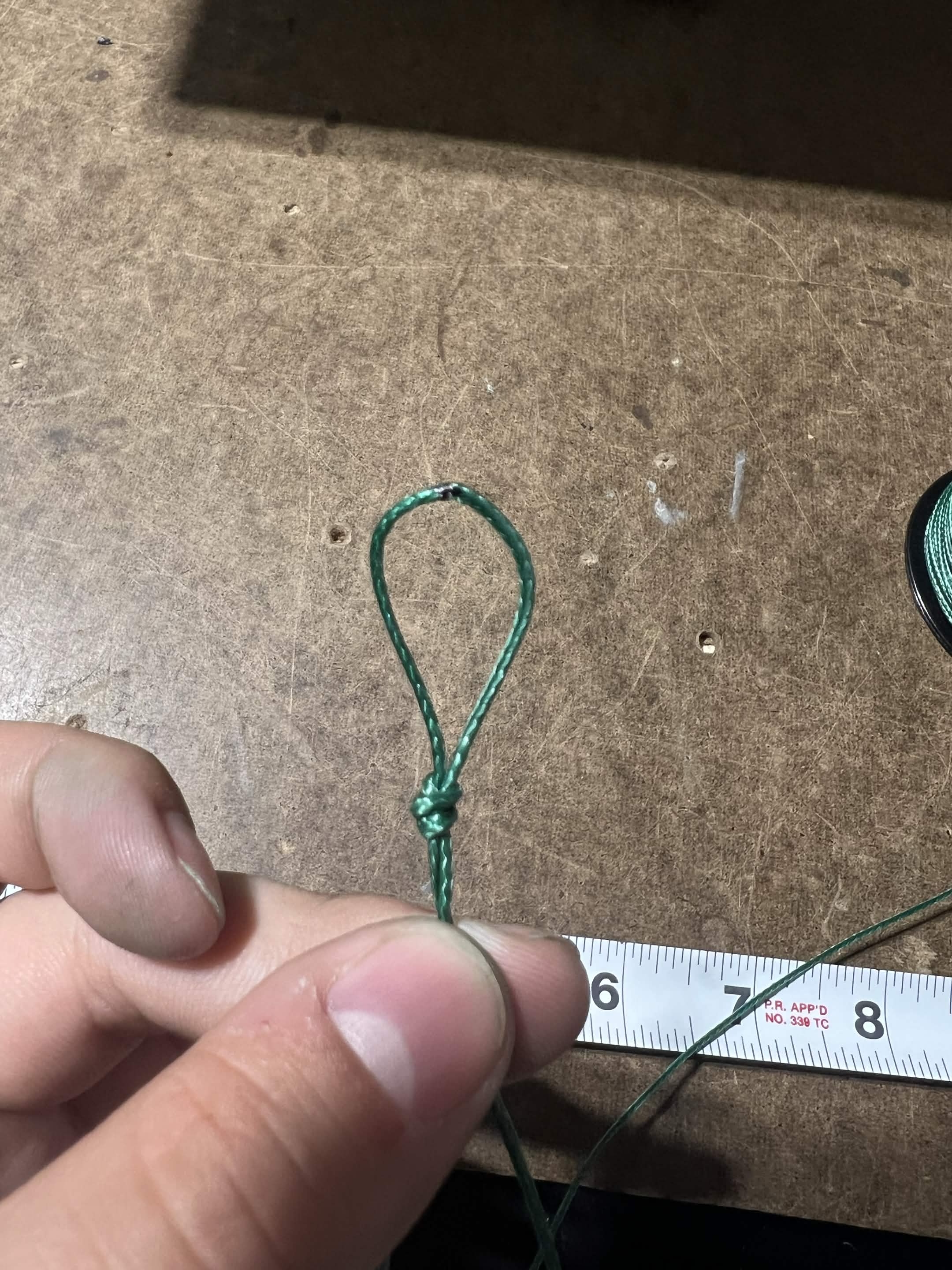
Completed end loop.
Cut the line free from the spool. Leave approximately 0.25 inch tail on the final knot.
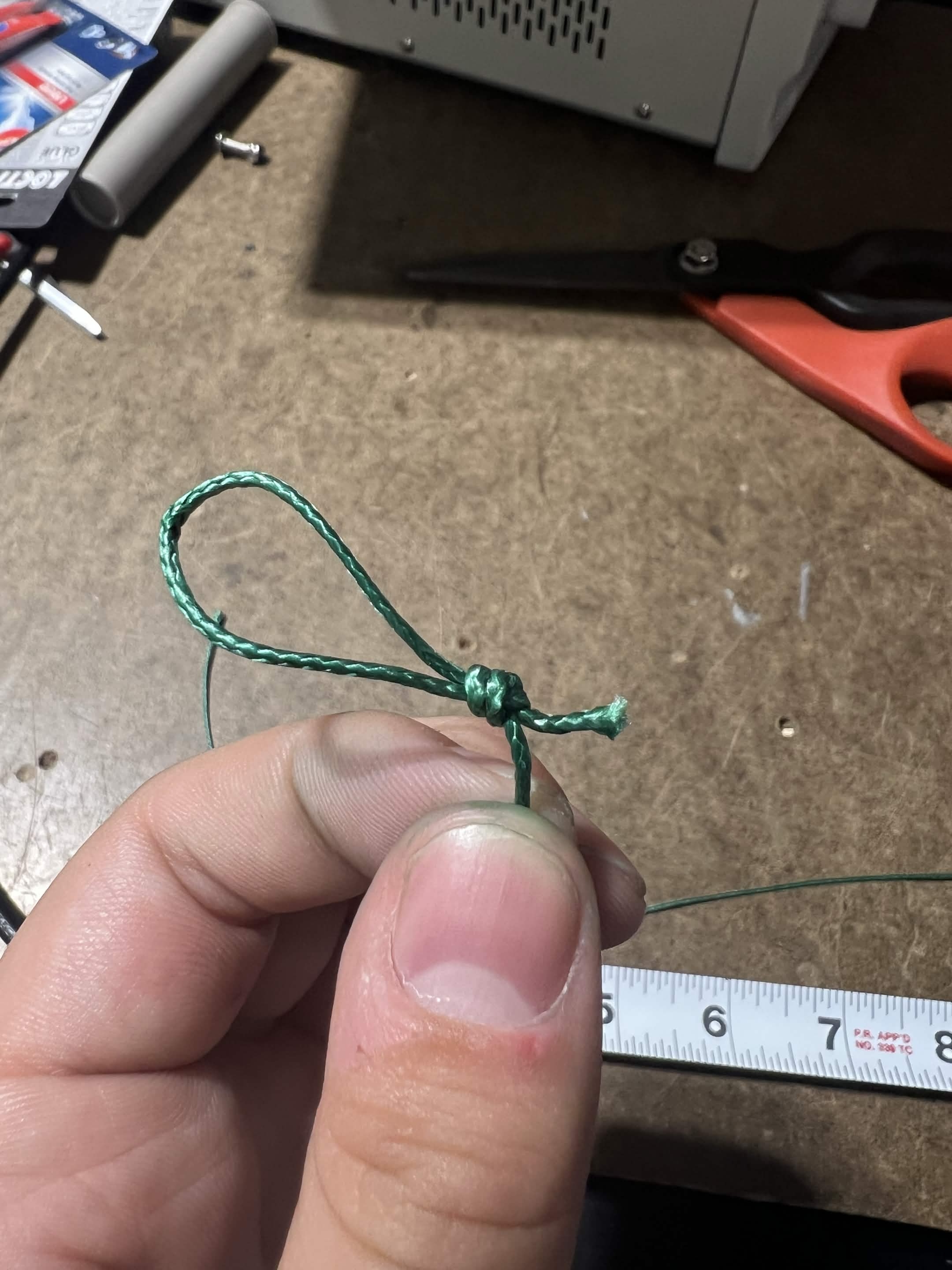
Trimmed end loop.
Verify the completed burnwire line length. Finished length of 12.75 ± 0.5 inches. Measure from loop tip to loop tip.
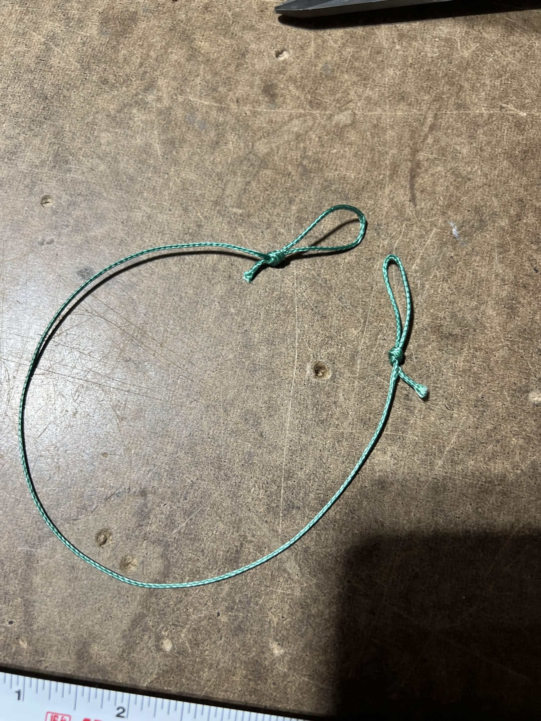
Completed burn-wire line.
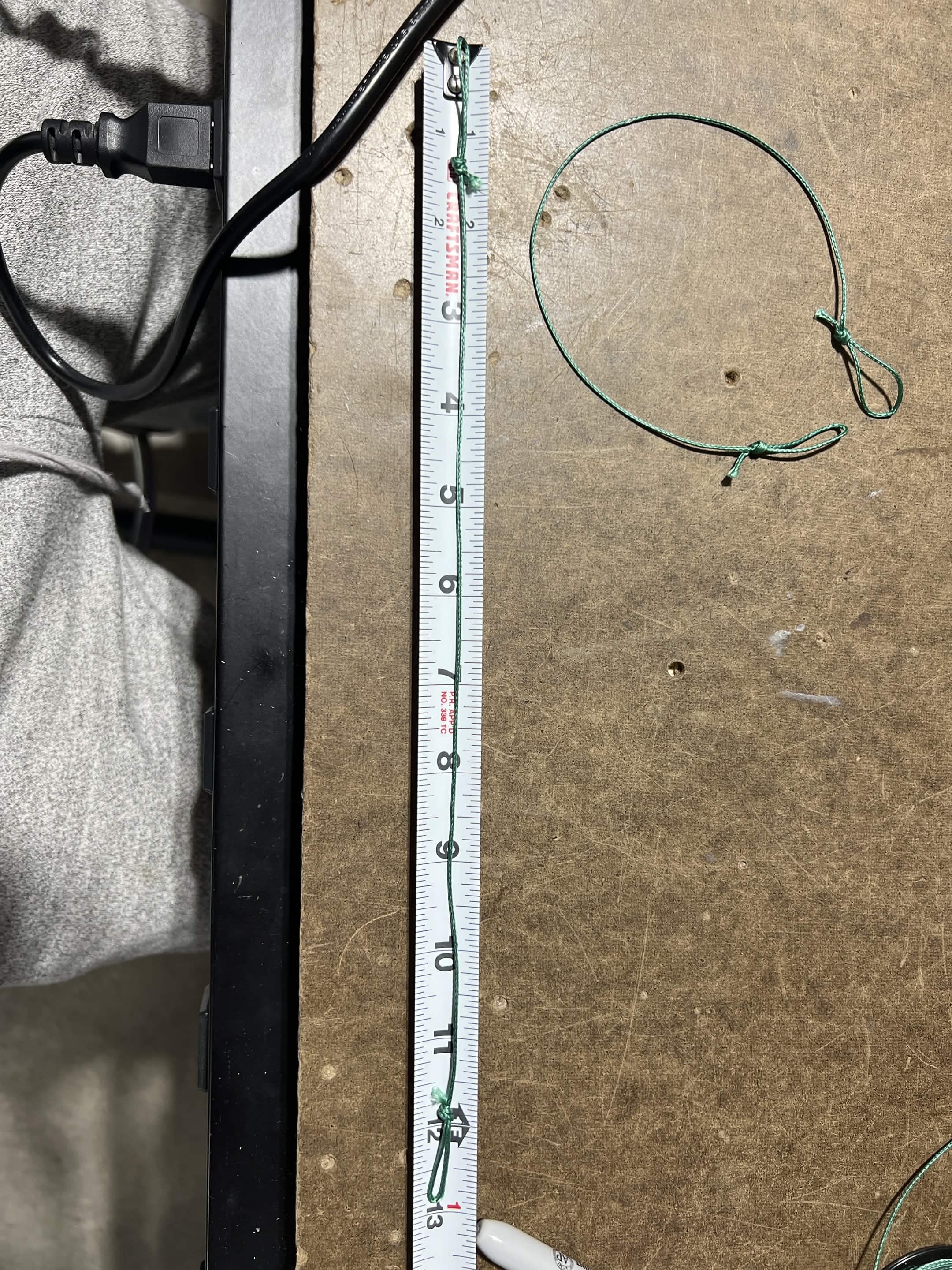
12.75in length confirmation.
A completed burnwire line is acceptable if:
| Qty | Value | Footprint | References |
|---|---|---|---|
| 6 | TestPoint | TestPoint:TestPoint_Bridge_Pitch2.0mm_Drill0.7mm | TP1, TP2, TP3, TP4, TP5, TP6 |
| 5 | ? | Resistor_SMD:R_1206_3216Metric_Pad1.30x1.75mm_HandSolder | R8, R9, R11, R12, R13 |
| 4 | 100k | Resistor_SMD:R_1206_3216Metric_Pad1.30x1.75mm_HandSolder | R3, R4, R5, R6 |
| 4 | 1u | Capacitor_SMD:C_1206_3216Metric_Pad1.33x1.80mm_HandSolder | C1, C2, C3, C4 |
| 3 | D24V7F3 | pcb:D24V7Fx | U1, U2, U3 |
| 2 | 1N4727A | Diode_THT:D_A-405_P7.62mm_Horizontal | D2, D4 |
| 2 | 3k | Resistor_SMD:R_1206_3216Metric_Pad1.30x1.75mm_HandSolder | R1, R2 |
| 2 | ? | Capacitor_SMD:C_1206_3216Metric_Pad1.33x1.80mm_HandSolder | C5, C7 |
| 2 | LOGO | LOGO | G***, G*** |
| 2 | WHITE | LED_SMD:LED_1206_3216Metric_Pad1.42x1.75mm_HandSolder | D1, D3 |
| 1 | 0 | Resistor_SMD:R_1206_3216Metric_Pad1.30x1.75mm_HandSolder | R14 |
| 1 | 10k | Resistor_SMD:R_1206_3216Metric_Pad1.30x1.75mm_HandSolder | R15 |
| 1 | 22u | Capacitor_SMD:C_1206_3216Metric_Pad1.33x1.80mm_HandSolder | C6 |
| 1 | 360k | Resistor_SMD:R_1206_3216Metric_Pad1.30x1.75mm_HandSolder | R10 |
| 1 | 910k | Resistor_SMD:R_1206_3216Metric_Pad1.30x1.75mm_HandSolder | R7 |
| 1 | BTS462TATMA1 | Package_TO_SOT_SMD:TO-252-4 | U4 |
| 1 | Conn_02x05_Top_Bottom | Connector_JST:JST_XH_S10B-XH-A_1x10_P2.50mm_Horizontal | J1 |
| 1 | GREEN | LED_SMD:LED_1206_3216Metric_Pad1.42x1.75mm_HandSolder | D6 |
| 1 | Housing | pcb:MainPowerDistributionSystemHousing | N1 |
| 1 | LM339 | Package_SO:SOIC-14_3.9x8.7mm_P1.27mm | U5 |
| 1 | RED | LED_SMD:LED_1206_3216Metric_Pad1.42x1.75mm_HandSolder | D5 |
| 1 | SolderJumper_2_Open | Jumper:SolderJumper-2_P1.3mm_Open_RoundedPad1.0x1.5mm | JP1 |
| 1 | ~ | pcb:MainStackConnector | J2 |
RockSat-X/RSXVT2026
Our experiment aims to evaluate the use of optical navigation with Commercial-off-the-Shelf (COTS) products for use in spaceflight applications.

RockSat-X/RSXVT2026
Our experiment aims to evaluate the use of optical navigation with Commercial-off-the-Shelf (COTS) products for use in spaceflight applications.

RockSat-X/RSXVT2026
Our experiment aims to evaluate the use of optical navigation with Commercial-off-the-Shelf (COTS) products for use in spaceflight applications.

RockSat-X/RSXVT2026
Our experiment aims to evaluate the use of optical navigation with Commercial-off-the-Shelf (COTS) products for use in spaceflight applications.

RockSat-X/RSXVT2026
Our experiment aims to evaluate the use of optical navigation with Commercial-off-the-Shelf (COTS) products for use in spaceflight applications.

RockSat-X/RSXVT2026
Our experiment aims to evaluate the use of optical navigation with Commercial-off-the-Shelf (COTS) products for use in spaceflight applications.

RockSat-X/RSXVT2026
Our experiment aims to evaluate the use of optical navigation with Commercial-off-the-Shelf (COTS) products for use in spaceflight applications.

RockSat-X/RSXVT2026
Our experiment aims to evaluate the use of optical navigation with Commercial-off-the-Shelf (COTS) products for use in spaceflight applications.

andrekuehne/openradfan
An ESPHome-driven controller for radiator fans to improve heat output

igonzalezb/tdse-tf_3-03
FIUBA - Electrónica - Taller de Sistemas Embebidos - Trabajo Final

Neumi/open_echo
Open Source echo sounder / depth sounder / SONAR for bathymetry and research. Arduino based and compatible.


ZeroPhone/ZeroPhone-PCBs
PCB files for ZeroPhone - for gerbers and schematics, go to "Releases" tab!

giant-axon/lu.i-neuron-pcb
Lu.i is an electronic neuron circuit mimicking and illustrating the basic dynamics of real, biological neurons. The printed circuit board (PCB) features a configurable, fully analog implementation of the leaky…

RobertPHeller/RPi-RRCircuits
A collection of circuit designs for various MCUs, not just Raspberry Pis relating to Model Railroading

listofoptions/TH-XWhatsIt
through hole implementation of the capsense controllers by XWhatsIt
It measures 66 × 60 mm and has 2 copper layers, 1.6 mm thick.
45 parts, built around the BTS462TATMA1, LM339 and 1N4727A. The full list of its parts is on this page, with links to each part's symbol and footprint where PCBKit's library has them.
From the RockSat-X/RSXVT2026 repository on GitHub, at the commit this page was made from: the board is pcb/MainPowerDistributionSystem.kicad_pcb and its schematic pcb/DebugBoard.kicad_sch. PCBKit opens the board in the browser, with nothing to install.
Its repository publishes it under the MIT licence: you may reuse it on that licence's terms (keep the author's notice, and for a copyleft licence share your changes alike).