
2 layers140 × 75 mm
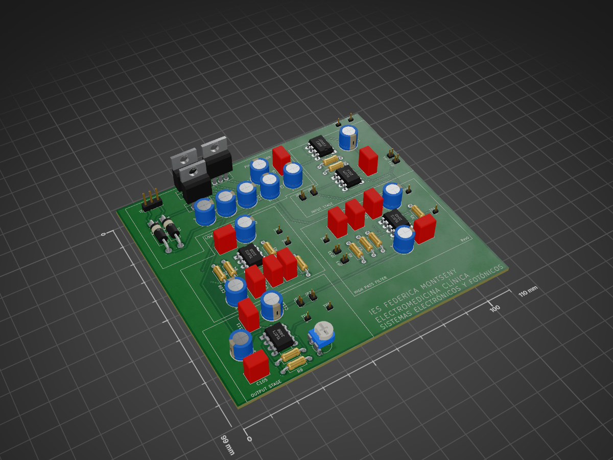
Simplified PCB of analog ECG used for educational purposes
ECG is an open-source printed circuit board by Rgarrido-RBN, from the Rgarrido-RBN/ECG repository on GitHub. It is a 2-layer board of 110 × 99 mm with 66 parts on 37 nets, routed with 280 tracks and 10 vias.
It is built around the TL072, L7805 and L7812, with the L7912 among its other parts. Its parts include 25 capacitors, 12 resistors, 8 ICs, 2 diodes and 1 connector.


Simplified PCB of analog ECG used for educational purposes
| Qty | Value | Footprint | References |
|---|---|---|---|
| 10 | 47u | Capacitor_THT:CP_Radial_D7.5mm_P2.50mm | C5, C7, C9, C10, C11, C12, C104, C106, C110, C112 |
| 10 | R | Resistor_THT:R_Axial_DIN0207_L6.3mm_D2.5mm_P10.16mm_Horizontal | R1, R2, R3, R4, R5, R6, R7, R8, R9, R10 |
| 8 | Jumper | Connector_PinHeader_1.27mm:PinHeader_1x02_P1.27mm_Vertical | JP1, JP2, JP3, JP4, JP11, JP22, JP33, JP44 |
| 6 | 100n | Capacitor_THT:C_Rect_L7.2mm_W4.5mm_P5.00mm_FKS2_FKP2_MKS2_MKP2 | C6, C8, C103, C105, C109, C111 |
| 6 | C | Capacitor_THT:C_Rect_L7.2mm_W4.5mm_P5.00mm_FKS2_FKP2_MKS2_MKP2 | C1, C2, C3, C4, C101, C107 |
| 3 | CP | Capacitor_THT:CP_Radial_D7.5mm_P2.50mm | C13, C102, C108 |
| 2 | D | Diode_THT:D_DO-15_P15.24mm_Horizontal | D1, D2 |
| 2 | TL071 | Package_DIP:DIP-8_W7.62mm_LongPads | U3, U5 |
| 2 | TL072 | Package_DIP:DIP-8_W7.62mm_LongPads | U1, U2 |
| 1 | AD623 | Package_DIP:DIP-8_W7.62mm_LongPads | U4 |
| 1 | AD623_OUT | Connector_PinHeader_1.27mm:PinHeader_1x01_P1.27mm_Vertical | TP9 |
| 1 | AMPLIFIER IN | Connector_PinHeader_1.27mm:PinHeader_1x01_P1.27mm_Vertical | TP5 |
| 1 | AMPLIFIER OUT | Connector_PinHeader_1.27mm:PinHeader_1x01_P1.27mm_Vertical | TP6 |
| 1 | Conn_01x03_Female | Connector_PinHeader_2.54mm:PinHeader_1x03_P2.54mm_Vertical | J1 |
| 1 | HighPass IN | Connector_PinHeader_1.27mm:PinHeader_1x01_P1.27mm_Vertical | TP2 |
| 1 | HighPass OUT | Connector_PinHeader_1.27mm:PinHeader_1x01_P1.27mm_Vertical | TP4 |
| 1 | IN + | Connector_PinHeader_1.27mm:PinHeader_1x01_P1.27mm_Vertical | TP8 |
| 1 | IN - | Connector_PinHeader_1.27mm:PinHeader_1x01_P1.27mm_Vertical | TP7 |
| 1 | L7805 | Package_TO_SOT_THT:TO-220-3_Vertical | U8 |
| 1 | L7812 | Package_TO_SOT_THT:TO-220-3_Vertical | U6 |
| 1 | L7912 | Package_TO_SOT_THT:TO-220-3_Vertical | U7 |
| 1 | LowPass IN | Connector_PinHeader_1.27mm:PinHeader_1x01_P1.27mm_Vertical | TP1 |
| 1 | LowPass OUT | Connector_PinHeader_1.27mm:PinHeader_1x01_P1.27mm_Vertical | TP3 |
| 1 | R_POT | Potentiometer_THT:Potentiometer_Piher_PT-6-V_Vertical | RV1 |
| 1 | Rg1 | Resistor_THT:R_Axial_DIN0207_L6.3mm_D2.5mm_P10.16mm_Horizontal | R11 |
| 1 | Rg2 | Resistor_THT:R_Axial_DIN0207_L6.3mm_D2.5mm_P10.16mm_Horizontal | R12 |


daanklijn/eurorack-psu
Eurorack Powersupply PCB // Can be built for 2$ @ JLCPCB

dario0603/power_supply
Progetto universitario per la realizzazione e simulazione di un Alimentatore da Banco Stabilizzato , completo di schemi elettrici KiCad, simulazioni LTspice, documentazione tecnica e file Gerber per la produzione del…

felipesantiagoach-ops/cdp1802-8bit-computer
8-bit microcomputer based on the RCA CDP1802, the first CMOS microprocessor. Three stages designed in KiCad: two built and tested (assembly programs, UART, Tiny BASIC, Elf/OS) and a final design with an ADC, I²C/SPI…

NaraenderHardware/pcb-design-manufacturing-engineering
PCB design, circuit development, and manufacturing engineering project files.
It measures 110 × 99 mm and has 2 copper layers, 1.6 mm thick.
66 parts, built around the TL072, L7805, L7812 and L7912. The full list of its parts is on this page, with links to each part's symbol and footprint where PCBKit's library has them.
From the Rgarrido-RBN/ECG repository on GitHub, at the commit this page was made from: the board is ecg.kicad_pcb. PCBKit opens the board in the browser, with nothing to install.
Its repository states no licence, so its author keeps all rights: ask Rgarrido-RBN before reusing the design.