4 layers142.5 × 86.6 mm

 RemiFM/VFD-Power-Supply2
Power supply for a vacuum fluorescent display.
Vfd display is an open-source printed circuit board by RemiFM, from the RemiFM/VFD-Power-Supply repository on GitHub. It is a 2-layer board of 154 × 54 mm with 80 parts on 50 nets, routed with 215 tracks and 107 vias.
It is built around the LM3478MA, LR12LG-G and BZT52B3V3, with the PJ-036AH-SMT-TR, SK220A and STD16N65M5 among its other parts. Its parts include 24 capacitors, 21 resistors, 6 diodes, 5 ICs and 3 connectors. It belongs with the lEDs and displays and power boards of this library.


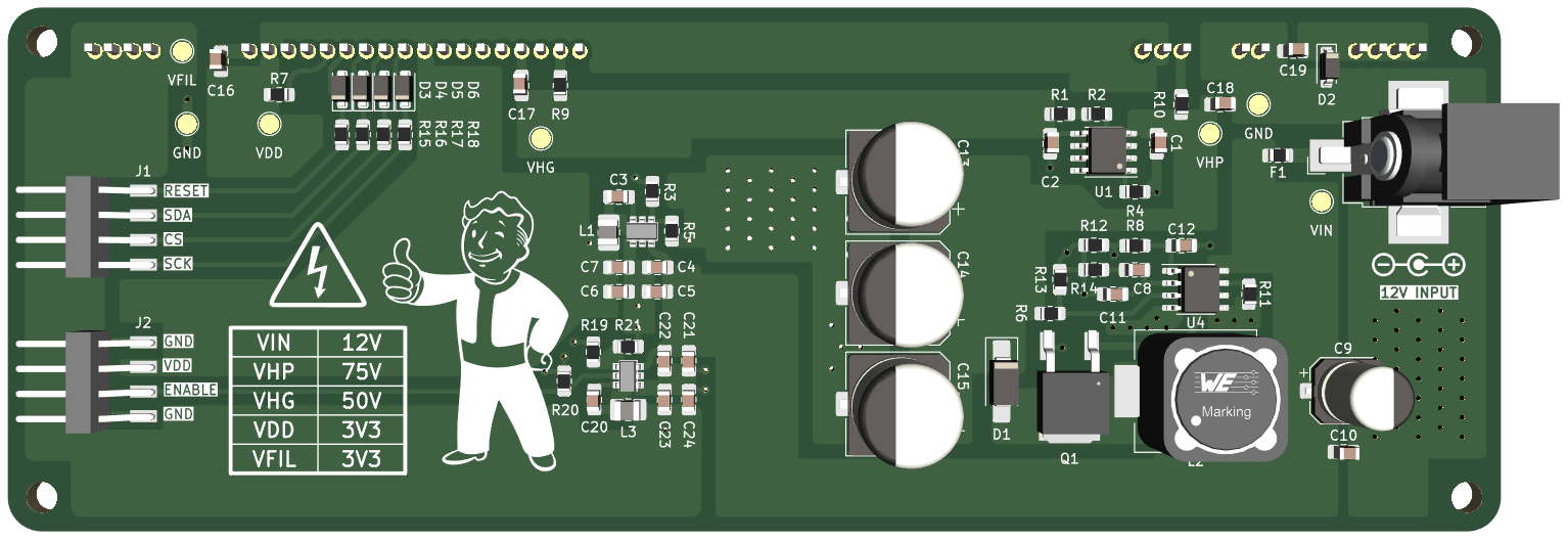
Power supply for the GP1294AI & GP1278BI (also marketed as VFD25648) vacuum fluorescent display. The supply requires a 12V input source, and outputs the necessary voltages to drive the anodes and filaments of the display.
[!CAUTION] The power supply outputs voltages up to 75V DC which can be hazardous. Handle with care.
The VFD Display can be soldered to the front of the PCB. All components of the power supply are surface-mount technology (SMT) and are placed on the backside of the PCB. Only connect the display to the PCB after verifying all voltages on the power supply using the provided measuring points. The display can be controlled using any microcontroller that uses 3V3 logic (ESP32, Raspberry Pi...) using the general purpose 2.54mm male headers on the board.
The production files necessary for manufacturing are bundled in the compressed folders export/GP1294AI.zip or export/GP1278BI.zip, depending on the specific VFD display used. The gerber files are generated according to the guidelines of fabrication house JLCPCB. It is recommended to order the PCB from JLCPCB by uploading the compressed folder to their website, but other manufacturers (PCBWay, Eurocircuits...) should work as well.
A bill of materials (BOM) is available for download. The BOM contains Digi-Key part numbers, and is formatted in a way that can be uploaded to the Digi-Key website for effortless ordering. Alternatively, the URL below leads to a public product list on Digi-Key which can be used for ordering the parts. As of June 2024, the total component cost is ~€23.
[!TIP] Order all necessary components by following this link.
For assembly, please make use of the provided schematic, available in pdf format.
| Qty | Value | Footprint | References |
|---|---|---|---|
| 9 | 100nF | Capacitor_SMD:C_0805_2012Metric_Pad1.18x1.45mm_HandSolder | C3, C5, C10, C16, C17, C18, C19, C20, C22 |
| 7 | TestPoint_Pad_D2.0mm | TestPoint:TestPoint_Pad_D2.0mm | GND, GND, VDD, VFIL, VHG, VHP, VIN |
| 4 | 10k | Resistor_SMD:R_0805_2012Metric_Pad1.20x1.40mm_HandSolder | R5, R13, R20, R21 |
| 4 | 22uF | Capacitor_SMD:C_0805_2012Metric_Pad1.18x1.45mm_HandSolder | C6, C7, C23, C24 |
| 4 | BZT52B3V3 | Diode_SMD:D_SOD-123F | D3, D4, D5, D6 |
| 4 | LOGO | LOGO | G***, G***, G***, G*** |
| 3 | 200R | Resistor_SMD:R_0805_2012Metric_Pad1.20x1.40mm_HandSolder | R16, R17, R18 |
| 3 | 47uF | Capacitor_SMD:CP_Elec_10x10.5 | C13, C14, C15 |
| 2 | 10R | Resistor_SMD:R_0805_2012Metric_Pad1.20x1.40mm_HandSolder | R9, R10 |
| 2 | 10uF | Capacitor_SMD:C_0805_2012Metric_Pad1.18x1.45mm_HandSolder | C4, C21 |
| 2 | 1uF | Capacitor_SMD:C_0805_2012Metric_Pad1.18x1.45mm_HandSolder | C1, C2 |
| 2 | 2.2 uH | Inductor_SMD:L_1008_2520Metric_Pad1.43x2.20mm_HandSolder | L1, L3 |
| 2 | 31k6 | Resistor_SMD:R_0805_2012Metric_Pad1.20x1.40mm_HandSolder | R3, R19 |
| 2 | AP62250WU-7 | Remi_Footprints:TSOT26 | U2, U5 |
| 2 | Conn_01x04 | Remi_Footprints:M20-8900405 | J1, J2 |
| 1 | 100R | Resistor_SMD:R_0805_2012Metric_Pad1.20x1.40mm_HandSolder | R8 |
| 1 | 100k | Resistor_SMD:R_0805_2012Metric_Pad1.20x1.40mm_HandSolder | R7 |
| 1 | 100m | Resistor_SMD:R_0805_2012Metric_Pad1.20x1.40mm_HandSolder | R12 |
| 1 | 100uF | Capacitor_SMD:CP_Elec_6.3x7.7 | C9 |
| 1 | 10pF | Capacitor_SMD:C_0805_2012Metric_Pad1.18x1.45mm_HandSolder | C12 |
| 1 | 220k | Resistor_SMD:R_0805_2012Metric_Pad1.20x1.40mm_HandSolder | R4 |
| 1 | 220uH | Inductor_SMD:L_Wuerth_WE-PD-Typ-LS_Handsoldering | L2 |
| 1 | 28k7 | Resistor_SMD:R_0805_2012Metric_Pad1.20x1.40mm_HandSolder | R11 |
| 1 | 330pF | Capacitor_SMD:C_0805_2012Metric_Pad1.18x1.45mm_HandSolder | C8 |
| 1 | 340k | Resistor_SMD:R_0805_2012Metric_Pad1.20x1.40mm_HandSolder | R14 |
| 1 | 39pF | Capacitor_SMD:C_0805_2012Metric_Pad1.18x1.45mm_HandSolder | C11 |
| 1 | 4 X 200R | Resistor_SMD:R_0805_2012Metric_Pad1.20x1.40mm_HandSolder | R15 |
| 1 | 4A | Fuse:Fuse_0805_2012Metric_Pad1.15x1.40mm_HandSolder | F1 |
| 1 | 56R | Resistor_SMD:R_0805_2012Metric_Pad1.20x1.40mm_HandSolder | R2 |
| 1 | 590k | Resistor_SMD:R_0805_2012Metric_Pad1.20x1.40mm_HandSolder | R6 |
| 1 | 5K6 | Resistor_SMD:R_0805_2012Metric_Pad1.20x1.40mm_HandSolder | R1 |
| 1 | GP1294AI | Remi_Footprints:VFD_GP1287BI | U3 |
| 1 | LM3478 | Package_SO:SOIC-8_3.9x4.9mm_P1.27mm | U4 |
| 1 | LR12LG-G | Package_SO:SOIC-8_3.9x4.9mm_P1.27mm | U1 |
| 1 | MMSZ5222BT1G | Diode_SMD:D_SOD-123 | D2 |
| 1 | PJ-036AH-SMT-TR | Connector_BarrelJack:BarrelJack_CUI_PJ-036AH-SMT_Horizontal | J3 |
| 1 | SK220A | Diode_SMD:D_SMA_Handsoldering | D1 |
| 1 | STD16N65M5 | Remi_Footprints:STD16N65M5 | Q1 |
The 75 most common of 80 parts.

Danzibob/Titania3
The project goal is to create a datalogger small and light enough for an 18mm A8-3 rocket, but capable enough to use as a backup logger for mid and high power flights.

Galacs/esp32s3-poc-devboard
ESP32-S3 based PoC board made to test step-down power supply design, 24v level shifter, crystal circuits and RF circuit

Galacs/motor-power-poc
A POC PCB to test circuit electrical protections and motor control schemes

unterdrueckt/OpenBlind32
ESP32-C3 (Super Mini) based controller for blinds / rafstore.


Hansolini/Take-home-Maglev-lab
A small lab for students in control engineering to learn control topics at home!
o7-machinehum/Hydroponic
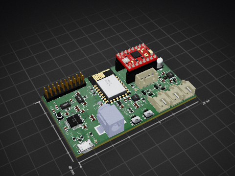
Please find the electronics files in the ee folder, all pcb design is done with the open source software KiCad. Is uses an STM32 as the main controller, and an ST L6470 moter driver for the stepper motor.
It measures 154 × 54 mm and has 2 copper layers, 1.6 mm thick.
80 parts, built around the LM3478MA, LR12LG-G, BZT52B3V3 and PJ-036AH-SMT-TR. The full list of its parts is on this page, with links to each part's symbol and footprint where PCBKit's library has them.
From the RemiFM/VFD-Power-Supply repository on GitHub, at the commit this page was made from: the board is vfd_display.kicad_pcb and its schematic vfd_display.kicad_sch. PCBKit opens the board in the browser, with nothing to install.
Its repository states no licence, so its author keeps all rights: ask RemiFM before reusing the design.