2 layers90 × 72 mm

 Reemuson/FIC-100A1
USB IR Adapter compatible with Fluke 287 and 289 series multimeters
FIC-100A is an open-source printed circuit board by Reemuson, from the Reemuson/FIC-100A repository on GitHub, published under the CERN-OHL-W-2.0 licence. It is a 2-layer board of 40 × 25 mm with 40 parts on 34 nets, routed with 167 tracks and 70 vias.
It is built around the FT231XS-U, LM393ADT and USBLC6-2SC6, with the LTST-C170KGKT, T491A475K025AT and PT334-6C among its other parts. Its parts include 12 resistors, 6 capacitors, 5 diodes, 3 ICs and 1 transistor. It belongs with the sensors and measurement and interfaces and adapters boards of this library.





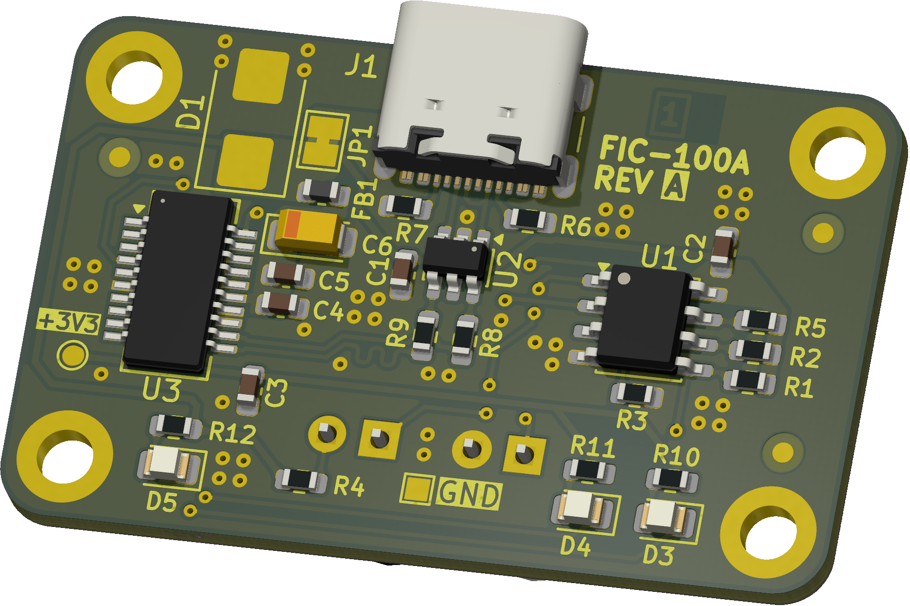
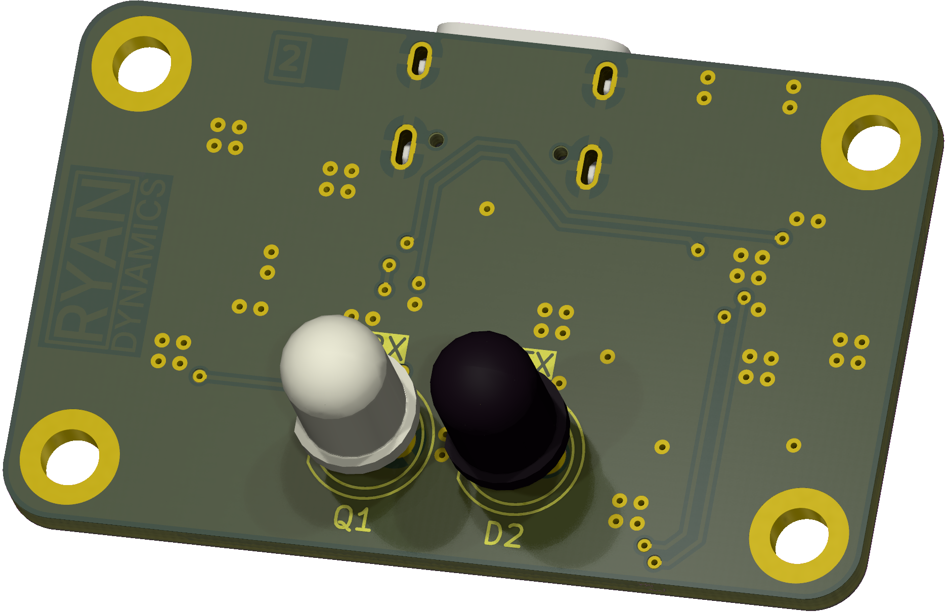
| Parameter | Value |
|---|---|
| Dimensions | 40.0 × 25.0 mm |
Public model identifier: FIC-100A
Recommended description: USB IR Adapter compatible with selected Fluke multimeters
This project uses a simple function-based product numbering style. FIC identifies the Fluke-compatible infrared cable family, and 100A identifies this product generation.
This project is an independent, third-party design compatible with selected Fluke instruments. It is not made by, endorsed by, sponsored by, or affiliated with Fluke Corporation. Fluke is a trademark of Fluke Corporation.
.
├─ Computations       # Misc calculations
├─ HTML               # HTML files for generated webpage
├─ Images             # Pictures and renders
│
├─ kibot_resources    # External resources for KiBot
│  ├─ colors          # Color theme for KiCad
│  ├─ fonts           # Fonts used in the project
│  ├─ scripts         # External scripts used with KiBot
│  └─ templates       # Templates for KiBot generated reports
│
├─ kibot_yaml         # KiBot YAML config files
├─ KiRI               # KiRI (PCB diff viewer) files
│
├─ lib                # KiCad footprint and symbol libraries
│  ├─ 3d_models       # Component 3D models
│  ├─ lib_fp          # Footprint libraries
│  └─ lib_sym         # Symbol libraries
│
├─ Logos              # Logos
│
├─ Manufacturing      # Assembly and fabrication documents
│  ├─ Assembly        # Assembly documents (BoM, pos, notes)
│ │This repository contains open hardware design files, protected project branding, and third-party workflow content.
CERN-OHL-W-2.0). See LICENSE.NOTICE.md.THIRD_PARTY_NOTICES.md.This project is an independent, third-party design compatible with selected Fluke instruments. It is not made by, endorsed by, sponsored by, or affiliated with Fluke Corporation. Fluke is a trademark of Fluke Corporation.
This is a hardware/electronics project. Anyone building, modifying, testing, selling, or using the design is responsible for verifying isolation, creepage and clearance, electrical safety, regulatory compliance, and fitness for purpose.
| Qty | Value | Footprint | References |
|---|---|---|---|
| 4 | 100n | Capacitor_SMD:C_0603_1608Metric | C1, C2, C3, C5 |
| 4 | MOUNT_M2.5 | MountingHole:MountingHole_2.7mm_M2.5_ISO7380_Pad | H1, H2, H3, H4 |
| 3 | 4.7k | Resistor_SMD:R_0603_1608Metric | R1, R2, R5 |
| 3 | FIDUCIAL | Fiducial:Fiducial_1mm_Mask2mm | FID1, FID2, FID3 |
| 3 | LED | LED_SMD:LED_0805_2012Metric | D3, D4, D5 |
| 2 | 27 | Resistor_SMD:R_0603_1608Metric | R8, R9 |
| 2 | 270 | Resistor_SMD:R_0603_1608Metric | R10, R11 |
| 2 | 5.11k | Resistor_SMD:R_0603_1608Metric | R6, R7 |
| 1 | +3V3 | RD-Testpoints:TestPoint_Pad_D1.0mm | TP2 |
| 1 | 10k | Resistor_SMD:R_0603_1608Metric | R3 |
| 1 | 10n | Capacitor_SMD:C_0603_1608Metric | C4 |
| 1 | 220 | Resistor_SMD:R_0603_1608Metric | R4 |
| 1 | 4.7u | Capacitor_Tantalum_SMD:CP_EIA-3216-18_Kemet-A | C6 |
| 1 | 619 | Resistor_SMD:R_0603_1608Metric | R12 |
| 1 | BLM18KG601BH1D | Inductor_SMD:L_0603_1608Metric | FB1 |
| 1 | BOARD_STACKUP_MARKER | RD-Symbols-Silkscreen:STACKUP_ID_2L_SML | ID1 |
| 1 | FT231XS-U | Package_SO:SSOP-20_3.9x8.7mm_P0.635mm | U3 |
| 1 | GND | RD-Testpoints:TestPoint_Pad_1.0x1.0mm | TP1 |
| 1 | LM393 | Package_SO:SOIC-8_3.9x4.9mm_P1.27mm | U1 |
| 1 | PT334-6C | LED_THT:LED_D5.0mm_Clear | Q1 |
| 1 | TSAL6100 | LED_THT:LED_D5.0mm_IRBlack | D2 |
| 1 | TVS | Diode_SMD:D_SMB | D1 |
| 1 | USB4105-GF-A | Connector_USB:USB_C_Receptacle_GCT_USB4105-xx-A_16P_TopMnt_Horizontal | J1 |
| 1 | USBLC6-2SC6 | Package_TO_SOT_SMD:SOT-23-6 | U2 |
| 1 | VUSB | Jumper:SolderJumper-2_P1.3mm_Bridged_Pad1.0x1.5mm | JP1 |


Reemuson/MENG4210-Project
Data Recording and Electrophysiological Acquisition Module

ARMontt/RedPink-CAN-USB
Device for Industrial - Automotive development


mjmorano/Precision-Current-Source
Once it's uploaded connect the Arduino pins to the 6 pin header on the current source as follows:


kekoraa/usb-c-pd-bench-breakout
USB-C PD trigger/breakout with selectable voltage requests and a routed two-layer KiCad PCB. Design-stage
It measures 40 × 25 mm and has 2 copper layers, 1.6 mm thick.
40 parts, built around the FT231XS-U, LM393ADT, USBLC6-2SC6 and LTST-C170KGKT. The full list of its parts is on this page, with links to each part's symbol and footprint where PCBKit's library has them.
From the Reemuson/FIC-100A repository on GitHub, at the commit this page was made from: the board is FIC-100A.kicad_pcb and its schematic Block Diagram.kicad_sch. PCBKit opens the board in the browser, with nothing to install.
Its repository publishes it under the CERN-OHL-W-2.0 licence: you may reuse it on that licence's terms (keep the author's notice, and for a copyleft licence share your changes alike).