4 layers38 × 70 mm
Dual converter power management module V1.0
Rack-Robotics/Powercore-V3
electrical-discharge power supply, open-source
71 parts85
 Rack-Robotics/Powercore-V385
electrical-discharge power supply, open-source
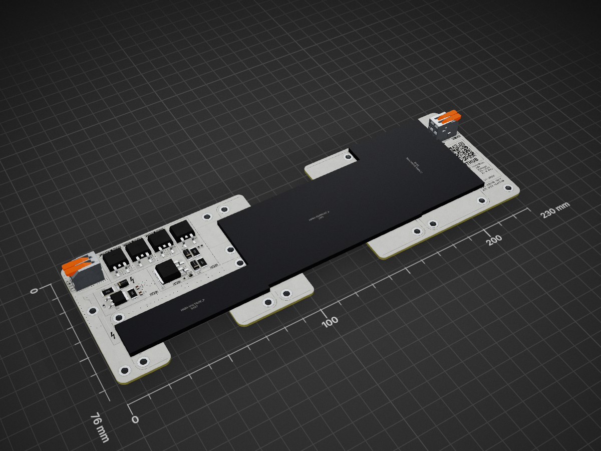
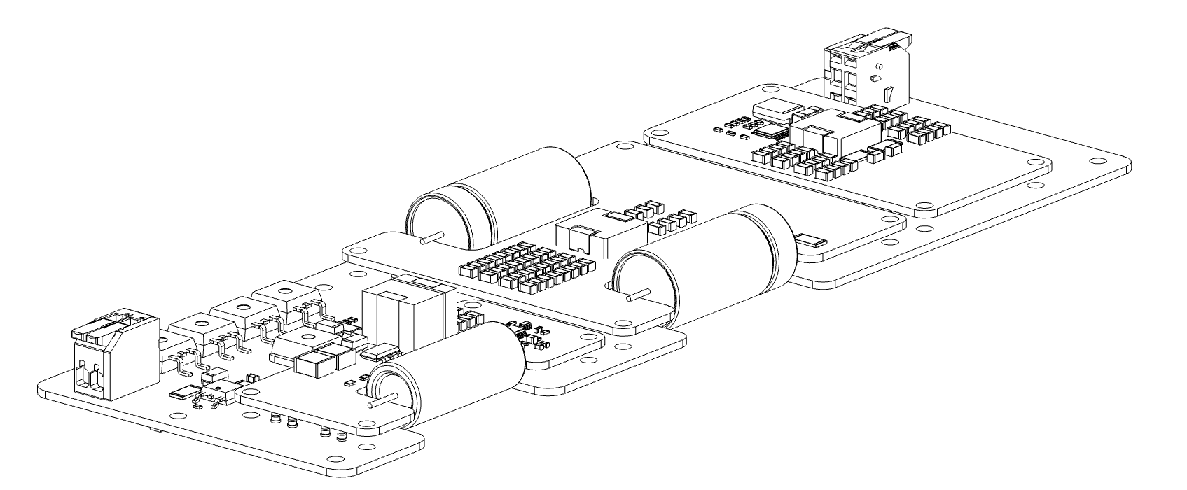
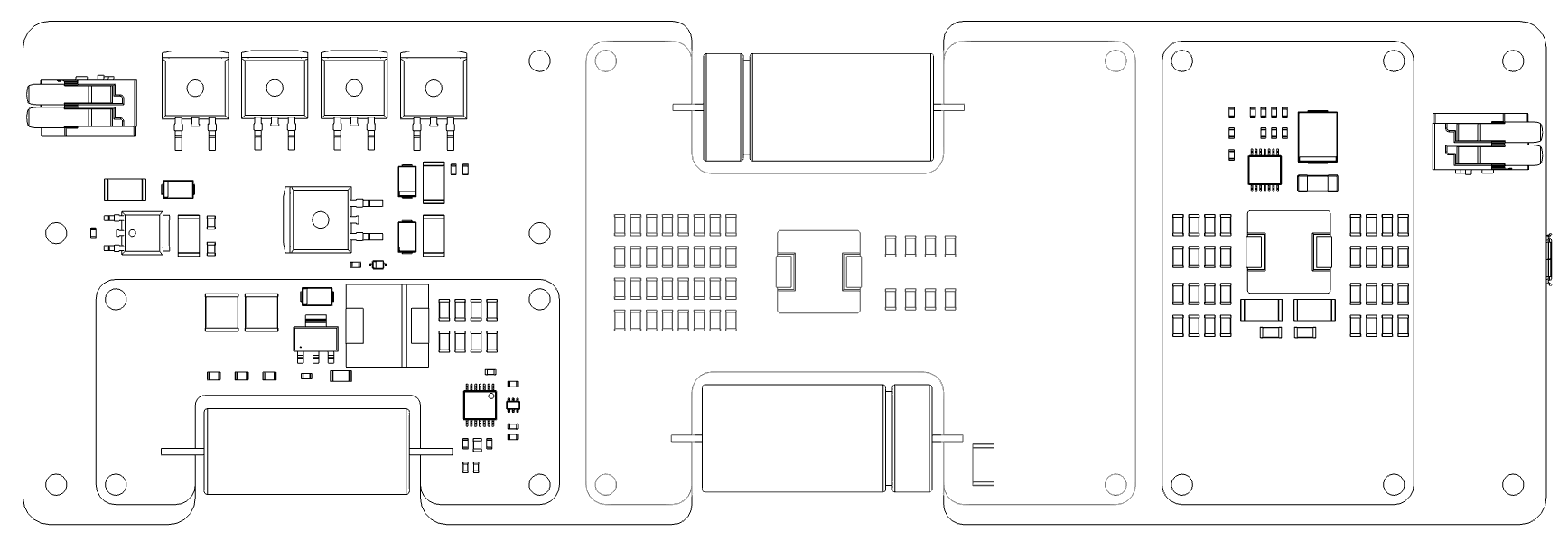
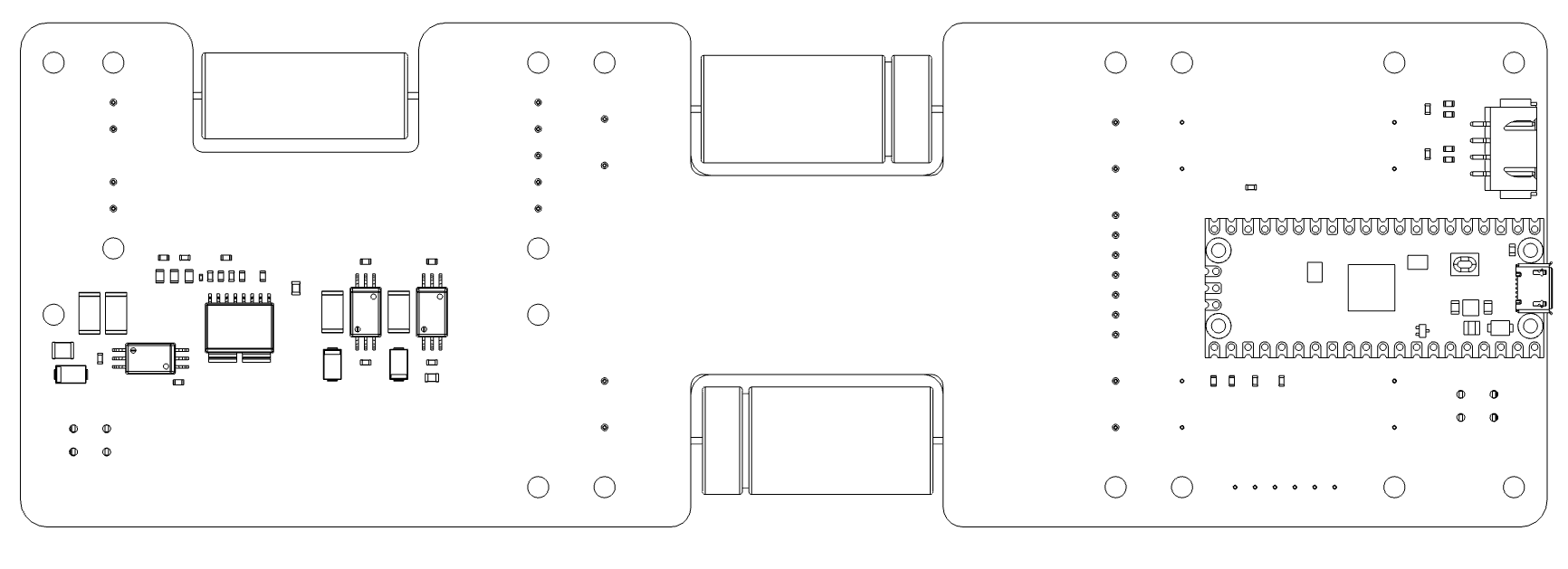
Dual converter motherboard V1.0 is an open-source printed circuit board by Rack-Robotics, from the Rack-Robotics/Powercore-V3 repository on GitHub. It is a 6-layer board of 230 × 76 mm with 130 parts on 75 nets, routed with 629 tracks and 555 vias.
It is built around the SC0915, UCC23313BDWYR and STPSC20065GY-TR, with the BBUP00100505330Y00, S4B-XH-SM4-TB and SIHB068N60EF-GE3 among its other parts. Its parts include 29 resistors, 16 capacitors, 10 diodes, 8 ICs and 3 transistors. It belongs with the power and computers and single-board computers boards of this library.


A high-efficiency power supply unit designed for Electrical Discharge Machining (EDM) applications.
circuit-boards/ - KiCAD PCB designs for all modulesschematics/ - Schematic PDFs for electronicsKiCAD-library/ - Custom component library and 3D modelsLTSpice/ - Simulation filespowercoreV3-firmware/ - Arduino firmware for the RP2040 controller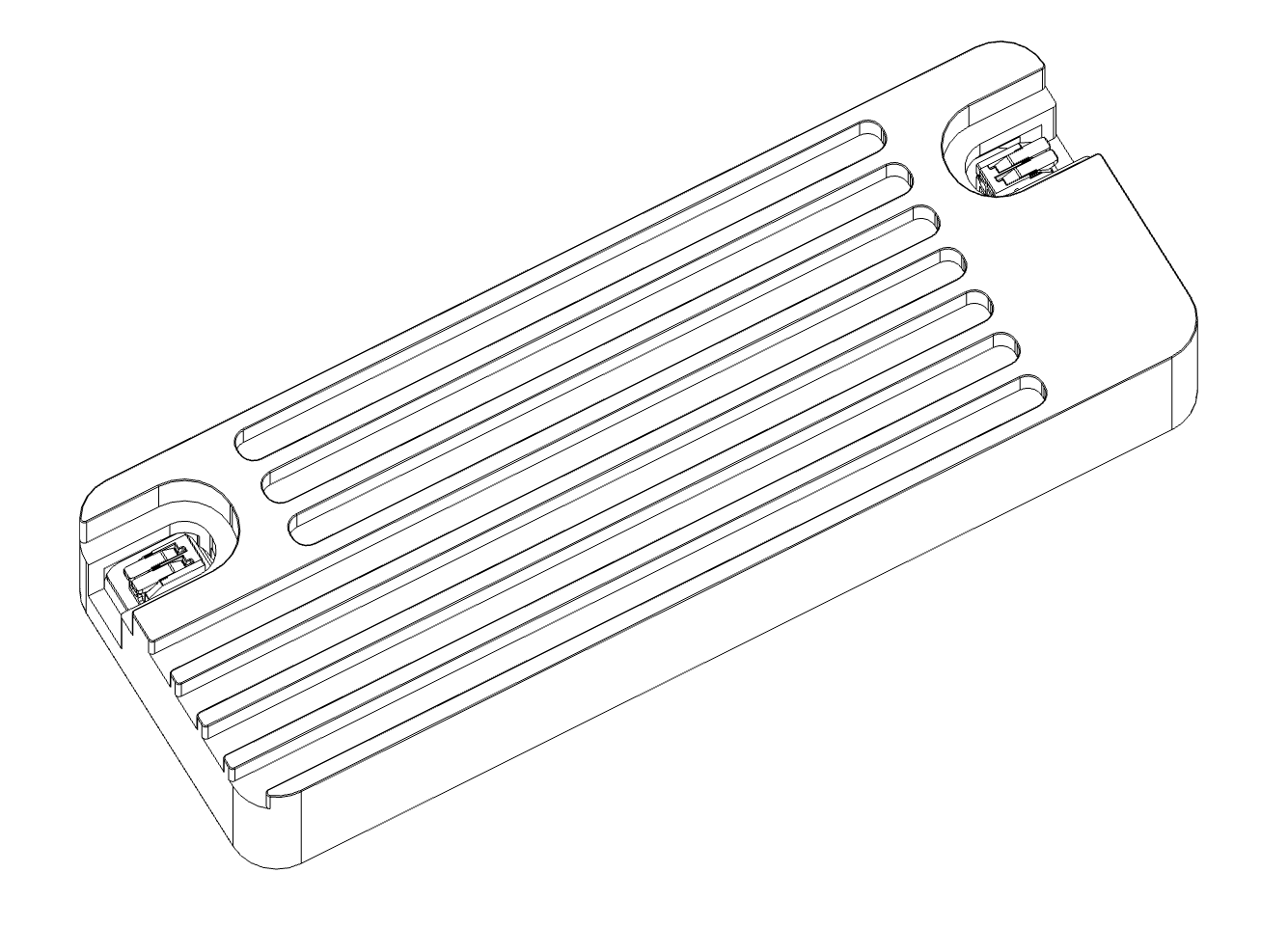
The Powercore V3 provides precision control of machining parameters including duty cycle, spark initiation voltage, and machining frequency. The system is optimized for desktop-scale wire EDM applications. The open-source design enables customization for research, development, and specialized EDM implementations.
| SPECIFICATION | Min | Max Value | UNIT |
|---|---|---|---|
| Average Input Power | 10 | 300 | W |
| Input Voltage | 47.8 | 48.2 | V |
| Input Current | 0.625 | 6.25 | A |
| Machining Duty Cycle | 1 | 10 | % |
| Spark Initiation Voltage | 64 | 100 | V |
| Machining Frequency | 5,000 | 10,000 | Hz |
| Machining Current (1) | 40 | 70 | A |
| PWM Feedback Duty Cycle | 0 | 100 | % |
| PWM Feedback Voltage | 0 | 3.3 | V |
| PWM Feedback Frequency | — | 1,000 | Hz |
| PWM Feedback Output Impedance | 1,010 | 9,990 | Ω |
| Enable Input Voltage | 3.0 | 3.5 | V |
| Enable Input Impedance | 1,010 | 9,990 | Ω |
(1) Machining current depends on output cable impedance and discharge characteristics. Not regulated by constant-current control. Lower-impedance output cables provide higher machining current.
| Parameter | Value |
|---|---|
| Ambient Temperature | 0°C to 30°C |
| Ingress Protection Rating | IP20 (Indoor use) |
| Relative Humidity | 20% to 80% (non-condensing) |
| Input Cable Gauge | 16 AWG minimum |
| Output Cable Gauge | 16 AWG stranded, 300V rated |
| Output Cable Length | <1 meter, twisted pair |
| Cooling | Forced air cooling recommended |
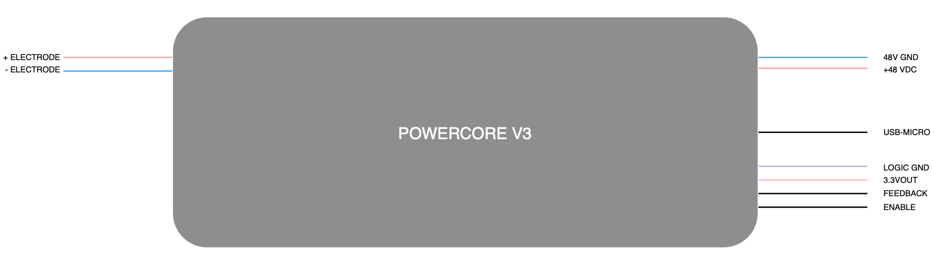
Input power connects via 2-position lever-action Wago connector accepting 16 AWG conductors. 48VDC input must be connected before applying 5V via USB-micro. If USB power is applied before 48VDC input, the microcontroller enters fault mode.
Output connects via 2-position lever-action Wago connector accepting 16 AWG stranded conductors. Output cable must be twisted pair, <1 meter length, and either shielded/grounded or contained within a shielded/grounded enclosure.
4-position JST-XH header provides communication with external controllers. Exposes 3.3V and GND from RP2040 microcontroller with current-limiting resistors.
Exposes USB-micro connector of RP2040 Pico module for parameter configuration and telemetry. Default baud rate: 115,200.
Warning: Device requires both 48VDC input power AND 5V USB power. 48VDC must be connected first, or device enters fault mode.
| SERIAL COMMAND | DESCRIPTION |
|---|---|
| SEND_TELEMETRY | Request device status and parameters |
| SET_ALL_PARAMETERS | Configure machining parameters: discharges, duty cycle, frequency, initiation voltage Format: 'SET_ALL_PARAMETERS [discharges] [duty_cycle] [frequency] [voltage]' Example: 'SET_ALL_PARAMETERS 0 0.10 5000 100' |
| EDM_ISOFREQUENCY_MODE | Enter EDM iso-frequency mode |
| EDGE_DETECTION_MODE | Enter edge detection mode |
| RESET_DEVICE | Reset device |
Invalid commands return list of valid commands.
The Powercore V3 generates controlled electrical discharges for EDM machining. The system cycles through spark initiation, current delivery, and discharge termination at high frequency (5-20kHz).
Spark Initiation Voltage: Determines spark formation conditions. Higher voltages create longer, more intense discharges suitable for harder materials.
Machining Duty Cycle: Controls discharge duration. Longer duty cycles increase material removal rate but may increase surface roughness.
Machining Frequency: Sets discharge repetition rate. Lower frequencies can increase material removal rate but may reduce surface finish quality.
Machining Current: Ranges from 40A to 70A, determined by fixed 48VDC output during current phase and combined impedance of output cables and discharge gap. Current is not user-adjustable.
On power-up, output is disabled (high-impedance state). Power management module initializes and pi-filter capacitors charge to 48V with inrush protection. Brief audible noise (~1 second) is normal during startup. Output current sensor calibrates and serial communication establishes.
BOOST CONVERTER SELF-TEST: System tests boost converter module and I2C digital potentiometer. If I2C communication fails, device reports 'ERROR: DPOT is not at expected position'.
During startup, digital potentiometer cycles through settings 0-110, generating boost converter output voltage lookup table (50V-160V). If voltage range is insufficient, device enters fault mode and reports 'ERROR: DPOT voltage range is less than expected'.
Normal startup sequence via serial:
Setting DPOT to minimum position...
Waiting for voltage to stabilize...
Reading voltages for DPOT lookup table...
Boost Converter Digital Potentiometer Voltage Table:
0: 51
1: 52
...
109: 161
110: 166
Successful startup indicated by solid green LED and "Setup complete" message. Device enters IDLE mode.
Output remains in high-impedance state until enable input is asserted (3.3V). No discharges occur in idle mode.
Fixed-frequency discharge mode. Default mode or activated via 'EDM_ISOFREQUENCY_MODE' command. Enable input must be asserted (3.3V) to begin operation.
ISO-FREQUENCY MODE PARAMETERS
| PARAMETER | Min | Default | Max | Unit |
|---|---|---|---|---|
| Machining Duty Cycle | 1 | 10 | 10 | % |
| Machining Frequency | 5,000 | 1,000 | 10,000 | Hz |
| Spark Initiation Voltage | 64 | 80 | 100 | V |
Probe mode for detecting electrode-workpiece contact via PWM feedback. Intended for setup and calibration only, not for machining. Activated via 'EDGE_DETECTION_MODE' command with enable input asserted.
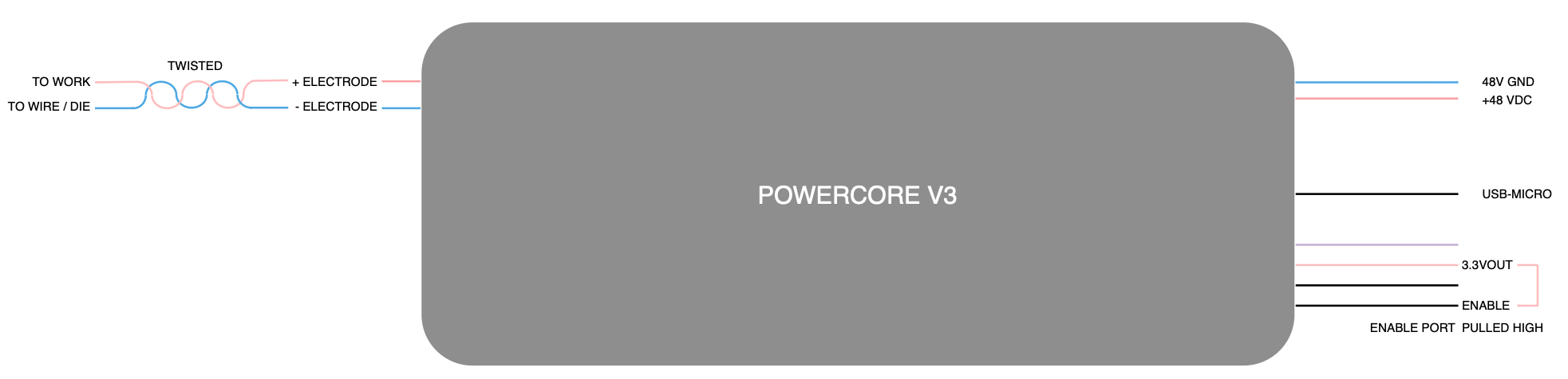
Minimum system configuration:
| Connection | Requirements |
|---|---|
| Power Input | 48V, 300W supply via 16 AWG stranded wire |
| USB-Micro | 5V supply or PC connection. Note: 48V must be connected first |
| Enable Input | Connect to 3.3V after power supplies are connected |
| Power Output | Positive (+) to workpiece, negative (-) to electrode (wire/tool) |
The Powercore V3 power supply unit is housed in a precision-machined, billet-aluminum enclosure, fully grounded to minimize electromagnetic interference. When no output cables are connected, radiated emissions are negligible. However, when output cables are attached, radiated emissions vary based on cable characteristics, including length, twist, and wire gauge.
Requirements: Output cables must be shielded, grounded, and twisted. Poor cable design may increase emissions and interfere with sensitive equipment.
Installation: Complete machining setup should be enclosed, shielded, and grounded. EMC compliance is installer's responsibility.

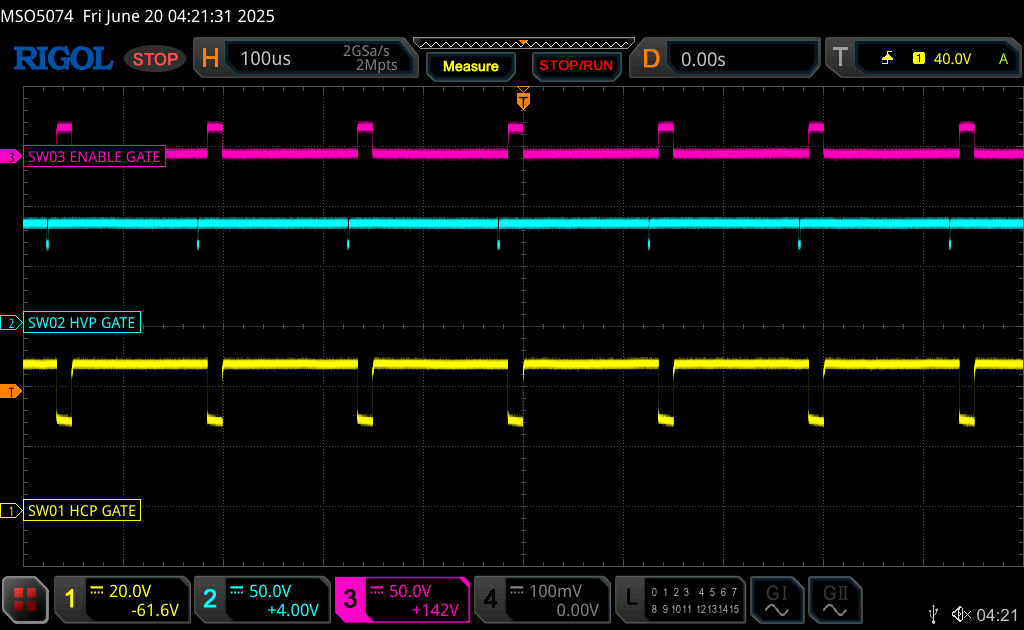
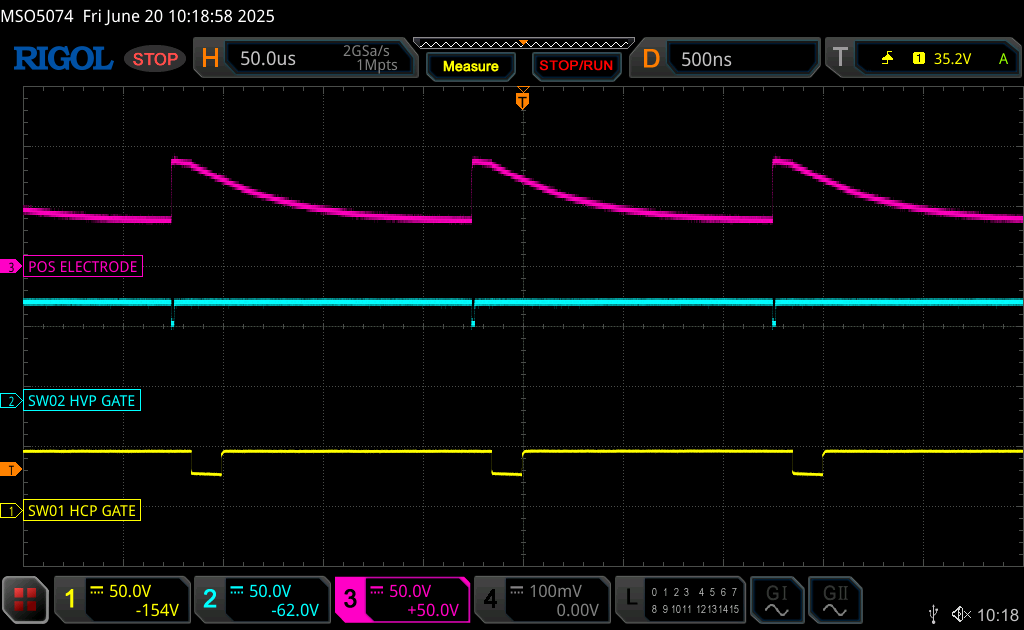
Normal behavior of output stage switches during EDM iso-frequency mode. The enable (yellow trace) and high-current phase (red trace) switches are both active at the same time, permitting current flow from the positive electrode to the negative electrode. The high-voltage switch is active several microseconds before each switching event, for the purpose of charging the output capacitor to the spark initiation voltage (blue trace).
Normal behavior of output stages during EDM iso-frequency mode, with the electrodes separated by several millimeters under distilled water. The positive (+) electrode (red trace) shows the change in gap voltage when the output capacitor is charged and then slowly discharged through the water.
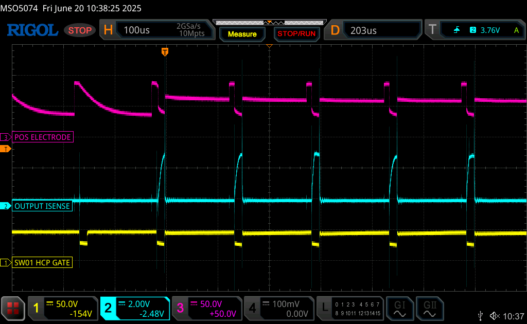
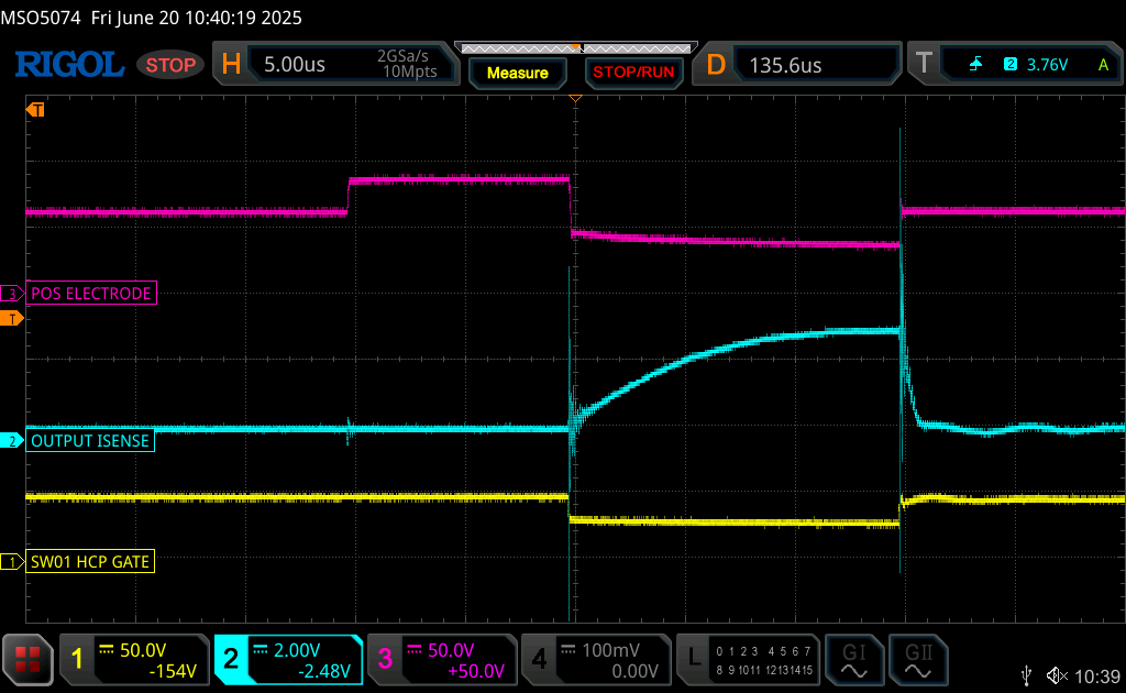
Normal behavior of output stages during EDM iso-frequency mode, during electrical discharge machining. The positive (+) electrode voltage changes rapidly during an EDM discharge; transitioning from the spark initiation voltage (here 80V) to the gap machining voltage (~40V) in several hundred nanoseconds.
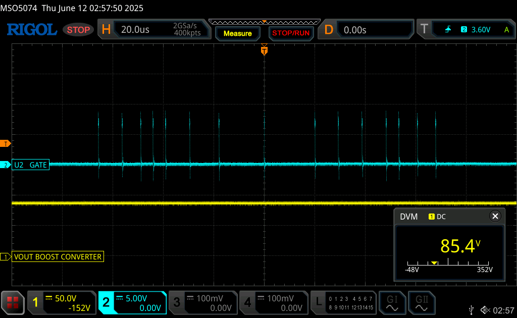
Normal behavior of the boost converter module. The MOSFET gate (blue trace) presents with short pulses, which are used to maintain a stable output voltage. The output voltage will be set by the I2C digital potentiometer to between 64 and 150 V.
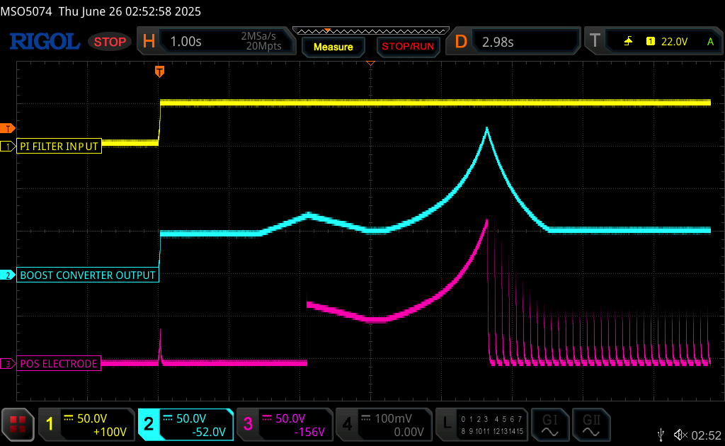
Startup behavior of device. Two seconds are required for inrush protection and serial communication initiation. Subsequently, the boost converter and output voltage sensor collaborate to create the lookup table for the I2C digital potentiometer. Once the lookup table is constructed, the boost converter is set to its default 80V setting.
The Powercore V3 2025 by Rack Robotics, Inc. is licensed under the Creative Commons Attribution-NonCommercial-ShareAlike 4.0 International License (CC BY-NC-SA 4.0).
You do not have to comply with the license for elements of the material in the public domain or where your use is permitted by an applicable exception or limitation.
No warranties are given. The license may not give you all of the permissions necessary for your intended use. For example, other rights such as publicity, privacy, or moral rights may limit how you use the material.
For the full license text, see: https://creativecommons.org/licenses/by-nc-sa/4.0/
This includes all hardware designs, firmware, documentation, and associated files in this repository. Commercial use requires explicit written permission from the project maintainers.
The name 'Powercore' and 'Rack Robotics' are property of Rack Robotics, Inc. and are only to be used by Rack Robotics, Inc. Any derivative works must remove both marks unless written permission to use either or both marks is provided by Rack Robotics, Inc.
DANGER - HIGH VOLTAGE PRESENT This device generates and outputs high-voltage DC, which could be hazardous. Before operating, building, or servicing this equipment, read and understand all safety warnings.
ELECTRICAL HAZARDS
LEGAL DISCLAIMER
| Qty | Value | Footprint | References |
|---|---|---|---|
| 30 | 0906-8-15-20-76-14-11-0 | powercore-development:0906-8-15-20-76-14-11-0 | POGO1, POGO2, POGO10, POGO11, POGO12, POGO13, POGO14, POGO15, POGO16, POGO17, POGO18, POGO19, POGO20, POGO21, POGO22, POGO23 +14 |
| 18 | M3_DIN | MountingHole:MountingHole_3.2mm_M3_DIN965_Pad_TopBottom | H1, H2, H3, H4, H5, H6, H7, H10, H11, H12, H13, H14, H15, H16, H17, H18 +2 |
| 8 | 10K | Resistor_SMD:R_0603_1608Metric | R3, R4, R12, R14, R17, R20, R21, R25 |
| 6 | 220 nF | Capacitor_SMD:C_0603_1608Metric | C1, C6, C8, C9, C10, C13 |
| 4 | 10000 pF | Capacitor_SMD:C_0603_1608Metric | C2, C14, C15, C16 |
| 3 | 10 nF | Capacitor_SMD:C_0805_2012Metric | C3, C4, C12 |
| 3 | 100R | Resistor_SMD:R_0603_1608Metric | R15, R19, R26 |
| 3 | 10R | Resistor_SMD:R_2512_6332Metric | R7, R9, R24 |
| 3 | 2.2K | Resistor_SMD:R_0603_1608Metric | R18, R28, R29 |
| 3 | 332K | Resistor_SMD:R_0805_2012Metric | R8, R10, R11 |
| 3 | D_Zener | Diode_SMD:D_SMA | D6, D7, D10 |
| 3 | STPSC20065GY-TR | powercore-development:STPSC20065GY-TR | D3, D4, D5 |
| 3 | UCC23313BDWYR | powercore-development:UCC23313BDWYR | U4, U6, U7 |
| 3 | US1M-13-F | Diode_SMD:D_SMA | D1, D2, D8 |
| 2 | 12K | Resistor_SMD:R_2512_6332Metric | R22, R23 |
| 2 | 1K | Resistor_SMD:R_2512_6332Metric | R16, R27 |
| 2 | 1K | Resistor_SMD:R_0603_1608Metric | R1, R2 |
| 2 | 255K | Resistor_SMD:R_0603_1608Metric | R5, R6 |
| 2 | 2601-1102 | powercore-development:2601-1102 | J1, J2 |
| 1 | 0.1 uF | Capacitor_SMD:C_1210_3225Metric | C11 |
| 1 | 0.47 uF | Capacitor_SMD:C_0805_2012Metric | C7 |
| 1 | 1R | Resistor_SMD:R_2512_6332Metric | R13 |
| 1 | BBUP00100505330Y00 | Inductor_SMD:L_0402_1005Metric | L1 |
| 1 | DMP45H4D9HK3-13 | powercore-development:DMP45H4D9HK3-13 | Q2 |
| 1 | D_Zener | Diode_SMD:D_SOD-323 | D9 |
| 1 | HIGH-CURRENT_PHASE_MODULE_V1.0 | powercore-development:HIGH-CURRENT_PHASE_MODULE_FOOTPRINT_V1.0 | U2 |
| 1 | HIGH-VOLTAGE_PHASE_MODULE | powercore-development:HIGH-VOLTAGE_PHASE_MODULE_FOOTPRINT_V1.0 | U3 |
| 1 | LOGO | powercore-development:powercoreV3github | G*** |
| 1 | POWER_MANAGEMENT_MODULE | powercore-development:POWER_MANAGEMENT_MODULE_FOOTPRINT_V1.0 | U1 |
| 1 | S4B-XH-SM4-TB | powercore-development:S4B-XH-SM4-TB | J3 |
| 1 | SC0915 | powercore-development:SC0915 | U8 |
| 1 | SIHB068N60EF-GE3 | Package_TO_SOT_SMD:TO-263-2 | Q3 |
| 1 | SUM110P08-11L-E3 | powercore-development:SUM110P08-11L-E3 | Q1 |
| 1 | TMCS1133C1A | powercore-development:TMCS1133C3AQDVGR | U5 |
| 1 | pF | Capacitor_SMD:C_0603_1608Metric | C5 |
The 119 most common of 130 parts.
Rack-Robotics/Powercore-V3
electrical-discharge power supply, open-source

Rack-Robotics/Powercore-V3
electrical-discharge power supply, open-source

Rack-Robotics/Powercore-V3
electrical-discharge power supply, open-source


psas/launch-tower
CAD files and software for the launch tower computer (LTC)

sOrzada/STASIS_Exposure_Hardware
This is the repository for the exposition hardware of the STASIS project.

aahmad-p/iot_tap_sensing
This repository contains an unorganized but complete copy of the code for an IoT Tap Sensing System.


geisel-m/NULunabotics
The repository for everything related to NU Lunabotics

gustebeast/public-steel-guitar
A pedal steel guitar you can build yourself, from parts anyone can buy.

It measures 230 × 76 mm and has 6 copper layers, 1.6 mm thick.
130 parts, built around the SC0915, UCC23313BDWYR, STPSC20065GY-TR and BBUP00100505330Y00. The full list of its parts is on this page, with links to each part's symbol and footprint where PCBKit's library has them.
From the Rack-Robotics/Powercore-V3 repository on GitHub, at the commit this page was made from: the board is circuit-boards/dual-converter-motherboard-V1.0/dual-converter-motherboard-V1.0.kicad_pcb and its schematic circuit-boards/dual-converter-boost-converter-module-V1.0/dual-converter-boost-converter-module-V1.0.kicad_sch. PCBKit opens the board in the browser, with nothing to install.
Its repository states no licence, so its author keeps all rights: ask Rack-Robotics before reusing the design.