2 layers44 × 22 mm
Batt swap
RIVeR-Lab/BOOST
Multi-Agent Mission Concept for Battery Optimized Onsite Swapping Technology (BOOST)
16 parts3MIT
 RIVeR-Lab/BOOST3
Multi-Agent Mission Concept for Battery Optimized Onsite Swapping Technology (BOOST)
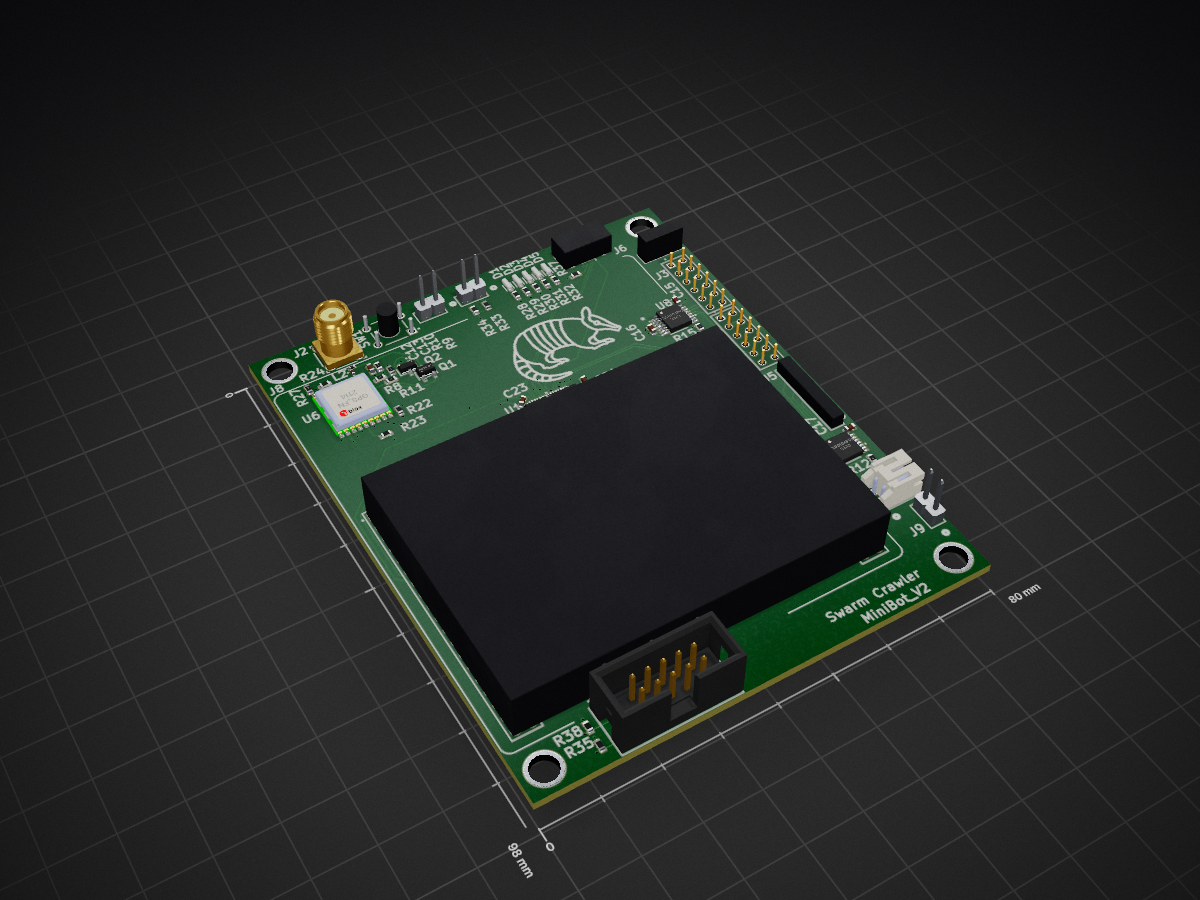
Minibot V1 is an open-source printed circuit board by RIVeR-Lab, from the RIVeR-Lab/BOOST repository on GitHub, published under the MIT licence. It is a 6-layer board of 80 × 98 mm with 101 parts on 104 nets, routed with 1,201 tracks and 159 vias.
It is built around the MP2148GQD-33-Z, BNO055 and 150060SS75000, with the CC0603KRX7R7BB104, CL31B106KOHNNWE and CBR04C220F5GAC among its other parts. Its parts include 34 resistors, 31 capacitors, 12 connectors, 8 ICs and 5 diodes. It belongs with the STM32 boards of this library.


/hubbot_software/
hubbot_software\ros2_ws\src\py_hubbot_main_controller_node\py_hubbot_main_controller_node/minibot_hubbot_firmware/charge_controller_firmware/
/minibot_hubbot_firmware/firmwarePioCube/
/shared/
/software/
./hubbot_software\start_hubbot_processes.sh
minibot_hubbot_firmware\charge_controller_firmware\monitor_RGBminibot_hubbot_firmware\firmwarePioCube\firmware_releases\hubbotminibot_hubbot_firmware\firmwarePioCube\firmware_releasesros2 topic pub /chatter std_msgs/String "data: Hello ROS Developers"
ros2 topic pub /hub_stat std_msgs/Int32 "data: 4"
$ sudo adduser myusername dialout
source ros1 roscore rosrun rosserial_python serial_node.py _port:=/dev/ttyACM0 _baud:=57600
source ros2 source ros1 ros2 run ros1_bridge dynamic_bridge --bridge-all-topics
| Qty | Value | Footprint | References |
|---|---|---|---|
| 19 | 0603 | Miscellaneous Devices.IntLib:J1-0603 | R1, R2, R4, R10, R11, R12, R13, R14, R15, R16, R17, R18, R19, R20, R21, R27 +3 |
| 15 | Res3 | Miscellaneous Devices.IntLib:J1-0603 | R22, R23, R24, R25, R26, R28, R29, R30, R31, R32, R33, R34, R35, R37, R38 |
| 8 | 0603 | Miscellaneous Devices.IntLib:1608[0603] | C9, C10, C11, C13, C14, C15, C16, C17 |
| 5 | 150060SS75000 | swarm_crawler_pcb.PcbLib:LED_150060SS75000 | D1, D2, D3, D4, D5 |
| 5 | CC0603KRX7R7BB104 | swarm_crawler_pcb.PcbLib:CC0603N_YAG | C21, C23, C24, C25, C26 |
| 4 | , , , | ||
| 4 | CL31B106KOHNNWE | swarm_crawler_pcb.PcbLib:CAP_CL31_SAM | C2, C4, C5, C6 |
| 3 | 61300211121 | swarm_crawler_pcb.PcbLib:CONN_61300211121_WRE | J7, J9, J10 |
| 2 | CBR04C220F5GAC | swarm_crawler_pcb.PcbLib:CAPC10555_55N_KEM | C7, C8 |
| 2 | Cap Semi | Miscellaneous Devices.IntLib:1608[0603] | C28, C29 |
| 2 | GRM1885C1H4R3BA01D | swarm_crawler_pcb.PcbLib:CAPC1608X90N | C30, C31 |
| 2 | GRM21BR71C475KE51L | swarm_crawler_pcb.PcbLib:CAP_GRM0805_2X1P25_MUR | C1, C3 |
| 2 | LP2981-33DBVR | swarm_crawler_pcb.PcbLib:DBV0005A_N | U2, U3 |
| 2 | TSW-106-07-F-D | swarm_crawler_pcb.PcbLib:SAMTEC_TSW-106-07-F-D | J3, J4 |
| 2 | TXB0104PWR | swarm_crawler_pcb.PcbLib:PW14 | U7, U8 |
| 2 | no stuff | swarm_crawler_pcb.PcbLib:CAP_CL31_SAM | C18, C19 |
| 1 | 1239AS-H-1R0M=P2 | swarm_crawler_pcb.PcbLib:CAPC10555_55N_KEM | L1 |
| 1 | 1825910-2 | swarm_crawler_pcb.PcbLib:TE_1825910-2 | SW1 |
| 1 | 22284036 | swarm_crawler_pcb.PcbLib:22-28-4036_MOL | J12 |
| 1 | 61201021621 | swarm_crawler_pcb.PcbLib:61201021621 | J11 |
| 1 | ABS25-32.768KHZ-1-T | swarm_crawler_pcb.PcbLib:ABS25-32.768KHZ-1-T_ABR | X2 |
| 1 | AO3407A | swarm_crawler_pcb.PcbLib:SOT-23-3L_AOS | Q1 |
| 1 | BNO055 | swarm_crawler_pcb.PcbLib:QFN_BNO055_BOS | U5 |
| 1 | C0603C0G1E270J030BA | swarm_crawler_pcb.PcbLib:CAP_0603_TDK | C12 |
| 1 | C1608X5R1C105K080AA | swarm_crawler_pcb.PcbLib:CAP_1608_TDK | C20 |
| 1 | C1608X5R1C225K080AB | swarm_crawler_pcb.PcbLib:CAP_1608_TDK | C27 |
| 1 | C1608X5R1C475K080AC | swarm_crawler_pcb.PcbLib:CAP_1608_TDK | C22 |
| 1 | ECS-.327-12.5-34B-C-TR | swarm_crawler_pcb.PcbLib:XTAL_ECS-.327-12.5-34B-C-TR | Y1 |
| 1 | GPS_FN | swarm_crawler_pcb.PcbLib:SL871 | U6 |
| 1 | MCR-B-S-RA-SMT-CS14-T_R | swarm_crawler_pcb.PcbLib:MCRBSRASMTCS14TR | J6 |
| 1 | MLG0603S36NJT000 | swarm_crawler_pcb.PcbLib:IND_0603_TDK | L2 |
| 1 | MP2148GQD-33-Z | swarm_crawler_pcb.PcbLib:QFN-1p0x1p5_MNP | U4 |
| 1 | NUCLEO-F446RE | swarm_crawler_pcb.PcbLib:MODULE_NUCLEO-F446RE | J8 |
| 1 | RF2-04A-T-00-50-G | swarm_crawler_pcb.PcbLib:CONN_RF2-04A-T-00-50-G_ADM | J2 |
| 1 | S2B-PH-K-S(LF)(SN) | swarm_crawler_pcb.PcbLib:CONN_S2B-PH-K-S_JST | J1 |
| 1 | SMMBT3904LT1G | swarm_crawler_pcb.PcbLib:SOT-23-3_1P4X3P040_ONS | Q2 |
| 1 | STM32F446RCT6TR | swarm_crawler_pcb.PcbLib:LQFP64-10x10mm | U1 |
| 1 | TSW-106-14-F-S | swarm_crawler_pcb.PcbLib:CON6_1X6_TU_TSW | J5 |
RIVeR-Lab/BOOST
Multi-Agent Mission Concept for Battery Optimized Onsite Swapping Technology (BOOST)

RIVeR-Lab/BOOST
Multi-Agent Mission Concept for Battery Optimized Onsite Swapping Technology (BOOST)

electromotif208/pcb-portfolio
👨💻 Electronics Engineer 📺 YouTube: ELECTROMOTIF 🔧 Tools: KiCad, EasyEDA 📡 Domains: Power Supply, ESP32, IoT, Embedded Hardware


M17-Project/Module_17
M17 modem board for 9600-baud capable radios

ts-manuel/iMX6-Demo-Board
Demo board for the i.MX6ULL Single-Core Processor with Arm Cortex-A7 Core

db-electronics/umd-nes-adapter-kicad
NES cartridge adapter for the Universal Mega Dumper


01binary/str1ker
A human-scale mech integrated with Robot Operating System

It measures 80 × 98 mm and has 6 copper layers, 1.6 mm thick.
101 parts, built around the MP2148GQD-33-Z, BNO055, 150060SS75000 and CC0603KRX7R7BB104. The full list of its parts is on this page, with links to each part's symbol and footprint where PCBKit's library has them.
From the RIVeR-Lab/BOOST repository on GitHub, at the commit this page was made from: the board is electrical/kicad/Minibot_V1/Minibot_V1.kicad_pcb and its schematic electrical/kicad/Minibot_V1/Connectors.kicad_sch. PCBKit opens the board in the browser, with nothing to install.
Its repository publishes it under the MIT licence: you may reuse it on that licence's terms (keep the author's notice, and for a copyleft licence share your changes alike).