

2 layers99.8 × 46.4 mm

 RBSC/OmniSCC23
OmniSCC catridge for MSX
OmniSCC+ is an open-source printed circuit board by RBSC, from the RBSC/OmniSCC repository on GitHub, published under the GPL-3.0 licence. It is a 2-layer board of 99.8 × 46.4 mm with 29 parts on 92 nets, routed with 574 tracks and 61 vias.
It is built around the SN74LVC8T245PW and RB520SM9-30. Its parts include 13 capacitors, 7 resistors, 4 ICs, 3 connectors and 1 diode. It belongs with the retro computing and games boards of this library.
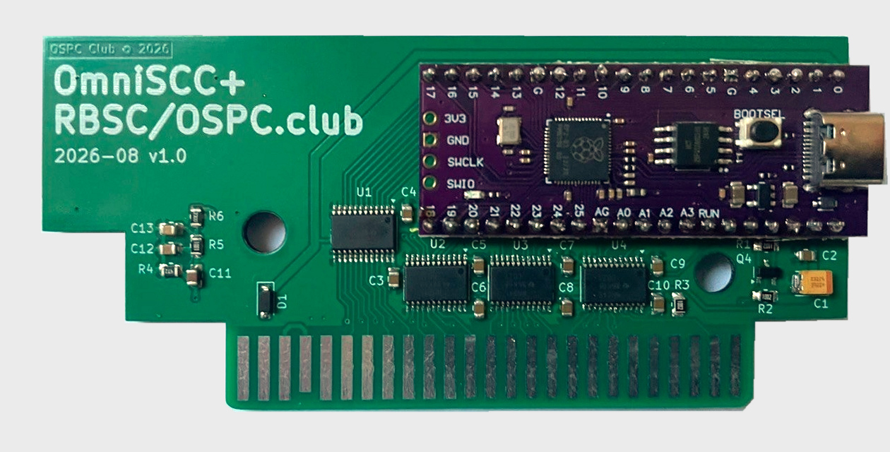
KiCad 8 project for OmniSCC+: the same 16 MB Raspberry Pi Pico clone, but with SN74LVC8T245 bus transceivers between the RP2040 and the MSX slot, so the MSX sees proper 5 V logic levels on the address, data and control lines.
R7 (10 kΩ, 0805) pulls /RES up to +5VA. This hardware change addresses
spontaneous resets observed in USB mode when touching the connector on revision
1.0. Use the revision 1.1 PCB and fabrication archive for new boards.
Revision 1.0 has no pull-up resistor on /RES. The floating reset signal can
cause spontaneous resets in USB mode, for example when touching the USB
connector. Add a 10 kΩ resistor between /RES and +5VA to retrofit the
pull-up included as R7 on revision 1.1.
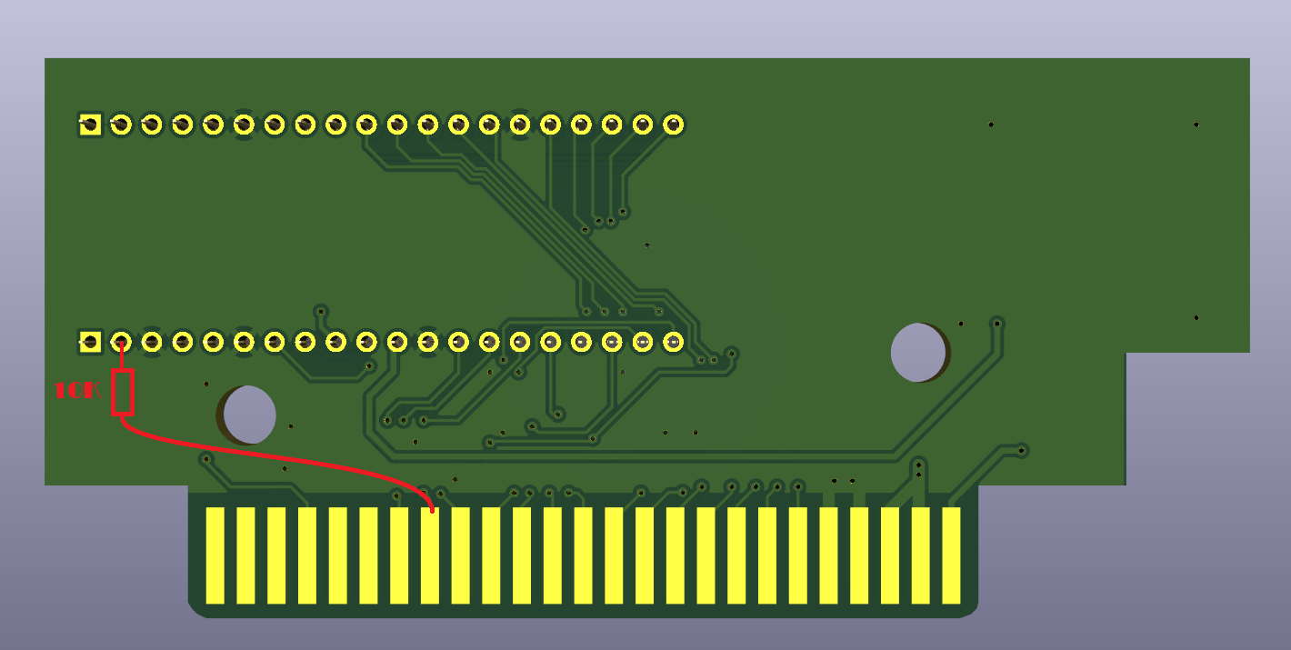
This is a hardware modification; changing the firmware alone does not add the pull-up. Revision 1.1 already includes R7 and needs no additional resistor.
| File | Contents |
|---|---|
OmniSCC+.kicad_sch / .kicad_pcb / .kicad_pro | Schematic, layout, project |
production/OmniSCCplus_1_1_Gerber.zip | Revision 1.1 Gerbers and drill files (no BOM/CPL) |
production/netlist.ipc | Revision 1.1 IPC-D-356 netlist for electrical test |
fabrication-toolkit-options.json | KiCad Fabrication Toolkit settings used to generate the ZIP |
Datasheets/OmniSCC+-v1.0-schematic.pdf | Historical revision 1.0 schematic; use the KiCad schematic for 1.1 |
Datasheets/RPPICOPURPLE-pin-1024x438.jpg | Pinout of the 16 MB Pico clone |
../../LICENSE | Project license |
The old production/OmniSCCplus_1_0_Gerber.zip and production/v1.0/ assembly
CSVs are retained for revision 1.0 only. They must not be used to assemble 1.1:
component positions changed and R7 was added. Generate new assembly exports
from the revision 1.1 KiCad project when needed.
Symbols and footprints come from the OSPC library (OSPC_Library); configure it before opening the project.
AUDIO, GP27 is the data transceiver direction
(DATA_DIR), GP28 is /WAIT. /IORQ, /BUSDIR, /M1 and /INT are not
routed to the RP2040.Build the firmware for this board with -DPICO_BOARD=omniscc_plus, which
defines WITH_SHIFTERS.
| Qty | Value | Footprint | References |
|---|---|---|---|
| 9 | 0.1uF | Capacitor_SMD:C_0805_2012Metric | C2, C3, C4, C5, C6, C7, C8, C9, C10 |
| 4 | 10K | Resistor_SMD:R_0805_2012Metric_Pad1.20x1.40mm_HandSolder | R1, R2, R3, R7 |
| 4 | SN74LVC8T245 | Package_SO:TSSOP-24_4.4x7.8mm_P0.65mm | U1, U2, U3, U4 |
| 2 | Conn_01x20 | Connector_PinSocket_2.54mm:PinSocket_1x20_P2.54mm_Vertical | J2, J3 |
| 1 | 10nF | Capacitor_SMD:C_0805_2012Metric | C13 |
| 1 | 10uF | Capacitor_SMD:C_0805_2012Metric | C11 |
| 1 | 1K | Resistor_SMD:R_0805_2012Metric | R5 |
| 1 | 22uF | Capacitor_Tantalum_SMD:CP_EIA-3528-21_Kemet-B | C1 |
| 1 | 2N7002 | Package_TO_SOT_SMD:SOT-23 | Q4 |
| 1 | 330 | Resistor_SMD:R_0805_2012Metric | R6 |
| 1 | 4.7nF | Capacitor_SMD:C_0805_2012Metric | C12 |
| 1 | 4K7 | Resistor_SMD:R_0805_2012Metric | R4 |
| 1 | Conn_MSX_BUS_edge | OSPC_Library:MSX_CART_SW_Small | J1 |
| 1 | RB520SM | Diode_SMD:D_SOD-123 | D1 |

pekkaroi/bldc-drive
Cheap and simple brushless DC motor driver designed for CNC applications using STM32 microcontroller

deltabeard/DBGC
A Game Boy cartridge using the Raspberry Pi RP2040 with RTC and MBC support.

KaiPereira/CM5-SODIMM-Carrier
A fully open source CM5 carrier to turn your Pi into a Jetson in compact SO-DIMM format!


squarewavedot/ledcubeelectronics
LEDCube battery and masterboard electronics


pekkaroi/ethernetcnc
This is my project for controlling CNC machine via ethernet port using LinuxCNC. It was originally shortly instroduced at http://pekka.eu/cnc.
It measures 99.8 × 46.4 mm and has 2 copper layers, 1.6 mm thick.
29 parts, built around the SN74LVC8T245PW and RB520SM9-30. The full list of its parts is on this page, with links to each part's symbol and footprint where PCBKit's library has them.
From the RBSC/OmniSCC repository on GitHub, at the commit this page was made from: the board is board/OmniSCC+/OmniSCC+.kicad_pcb and its schematic board/OmniSCC+/OmniSCC+.kicad_sch. PCBKit opens the board in the browser, with nothing to install.
Its repository publishes it under the GPL-3.0 licence: you may reuse it on that licence's terms (keep the author's notice, and for a copyleft licence share your changes alike).