Skip to the content
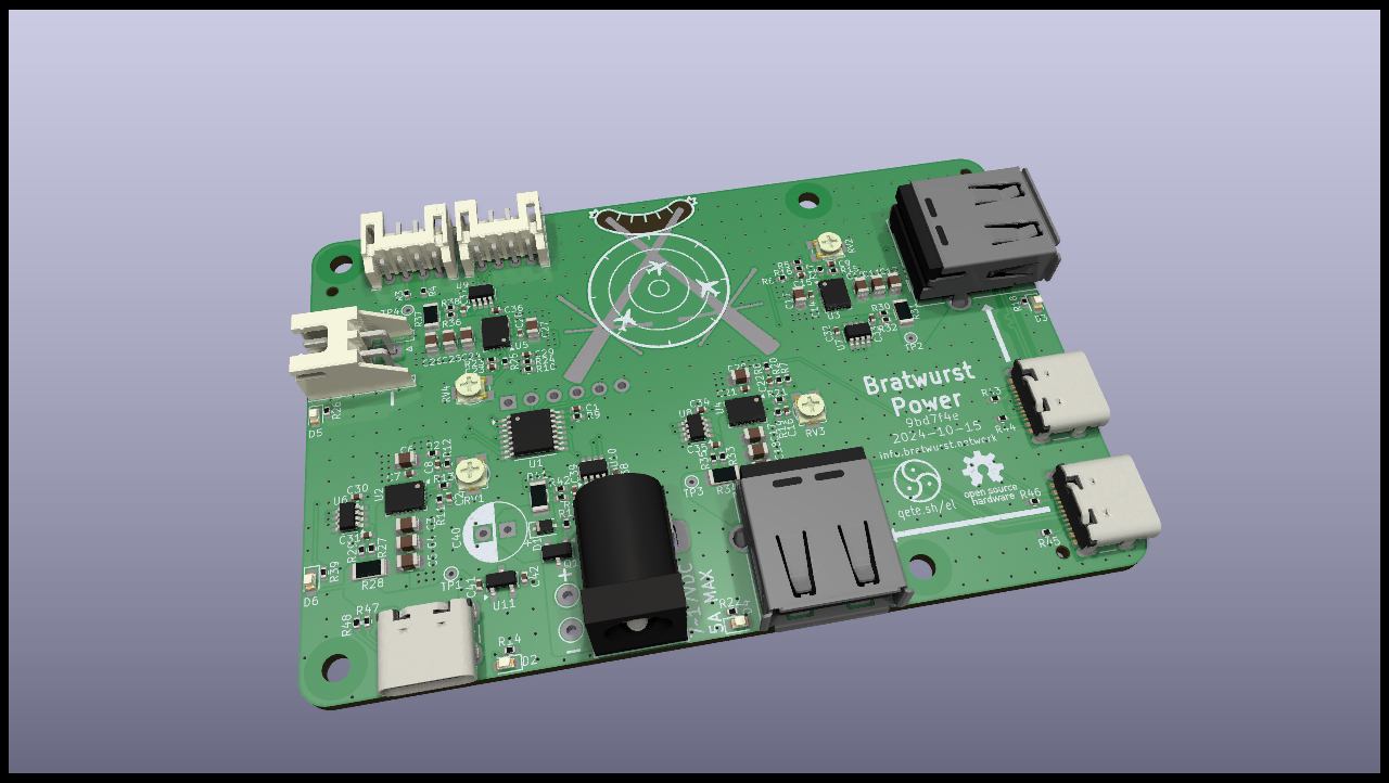
4 layers85 × 56 mmBratwurstPower, the printed circuit board in 3D

A power supply for a complete, Raspberry Pi based ADS-B Receiver Setup with independent power rails for the different components.

Size
85 × 56 mm
Copper layers
4
Thickness
1.61 mm
Parts
143
Nets
123
Pads
573
Tracks, vias
619, 588
Pours
42
Routed
Yes
KiCad
KiCad 8.0 (file 20240108)
Created
8 Sep 2024
Updated
26 Oct 2024

Overview

BratwurstPower is an open-source printed circuit board by Qeteshpony, from the Qeteshpony/BratwurstPower repository on GitHub, published under the BSD-2-Clause licence. It is a 4-layer board of 85 × 56 mm with 143 parts on 123 nets, routed with 619 tracks and 588 vias.

It is built around the PCA9557PW, XC6206P332MR-G and HL3415A, with the MM3Z10 among its other parts. Its parts include 48 resistors, 42 capacitors, 11 ICs, 11 connectors and 6 diodes. It belongs with the power boards of this library.

Main components

4

README

README.md

BratwurstPower

CI

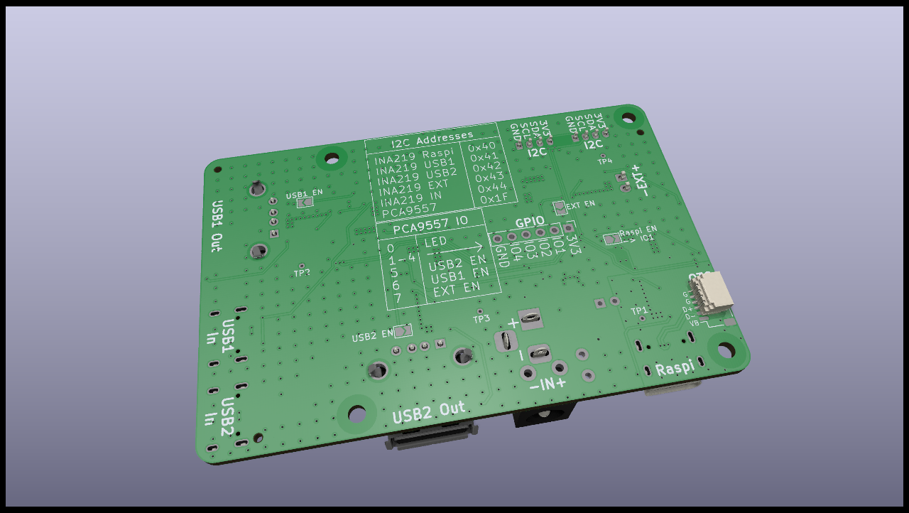
3D Render Top 3D Render Bottom

Hardware Documentation

What's this?

A power supply for a complete, Raspberry Pi based ADS-B Receiver Setup with independent power rails for the different components.

We sometimes face the problem that a normal Raspberry Pi power supply does not deliver enough power for the Raspi itself, the SDR Stick and possible other components like a display or even an SSD.

This board can be mounted underneath a Raspberry Pi and deliver stable 5.x V with up to 3 A to it.

In addition to that it can supply two USB devices and another external device with also 5.x V and 3 A each, provided the input has enough power and the maximum input current does not surpass 5A.

Each outputs voltage can be calibrated from ~5.06 to ~5.6 V with a trimpot and the two USB outputs are passing USB2 signals from two USB-C connectors that can be hooked up to the Raspberry Pi. If you need USB3, you can use an external Y-cable.

What else is on the board?

The onboard circuitry is powered by its own 3.3V LDO regulator which is fed by the power rail for the Raspberry Pi since that one is always running. The LDO can provide a maximum of 200mA to also power small external loads on the GPIO connector.

There is an INA219 power monitor connected to the main input and each output with a 10mΩ shunt resistor to measure current and voltage.

The onboard I2C bus is connected to all of the INA219 and a PCA9557

DeviceI2C-Address
INA219 Raspi0x40
INA219 USB10x41
INA219 USB20x42
INA219 EXT0x43
INA219 Main0x44
PCA95570x1F

The PCA9557 I/O expander allows to switch off power to the USB-ports and the external power. It also has an LED connected that can be used for showing a warning state or similar. The other 4 pins are broken out on a header.

PCA9557 PinFunction
IO0LED
IO1GPIO 1 (Opt: Raspi EN)
IO2GPIO 2
IO3GPIO 3
IO4GPIO 4
IO5USB2 EN
IO6USB1 EN
IO7EXT EN

Each voltage channel has a solder jumper to force-enable it. The USB power rails are also enabled as soon as their input usb port gets connected to the Raspberry Pi. In addition to that, all three external power connections can be controlled by the PCA9557 and there is an optional connection through a solder jumper to even give control over the Raspberry Pi power supply in case the I2C components on this board are controlled externally e.g. by an ESP.

External connections and jumpers

DesignatorFunction
INMain Power supply - can be powered with 7 to 17V DC with a maximum of 5A. Nominal Power: 12V.
RaspiPower supply for the Raspberry Pi. This is the only port that is by default always on.
USB1/2 inUSB input for external connections. Connect these to the Raspberry pi with normal USB cables.
USB1/2 outPowered USB output for external components, each with its own power supply.
EXTPower supply for other external components, also independently powered. Needs to be enabled through its solder jumper or by the PCA9557.
2x I2CI2C connection to either the Raspberry Pi or an external controller. The 3.3V connection is just a path-through between the connectors.
OTGOptional connector to access the Raspberry Pis USB-OTG functionality.
GPIOOptional header to use the free pins of the PCA9557. Keep in mind that the onboard 3.3V LDO can not provide more than 200mA.
USB1/2 ENSolder jumper to force-enable the USB power supplies in case you want to use them without a connection to the Raspberry Pi.
EXT ENSolder jumper to enable the EXT power supply.
Raspi ENSolder jumper to connect the EN pin if the Raspi power supply with IO1 of the PCA9557. This can be used to externally hard-reset the Raspberry Pi and should only be used when the board is controlled by an external controller like an ESP.
TP1Test point to measure the voltage on the Raspberry Pi power supply.
TP2Test point to measure the voltage on the USB1 power supply.
TP3Test point to measure the voltage on the USB2 power supply.
TP4Test point to measure the voltage on the EXT power supply.
RV1Calibration Potentiometer for the Raspberry Pi power supply.
RV2Calibration Potentiometer for the USB1 power supply.
RV3Calibration Potentiometer for the USB2 power supply.
RV4Calibration Potentiometer for the EXT power supply.

Software

Example software to control and monitor this device with Home Assistant can be found here.

Parts

143
QtyValueFootprintReferences
15100nCapacitor_SMD:C_0402_1005MetricC1, C7, C14, C21, C28, C30, C31, C32, C33, C34, C35, C36, C37, C38, C39
1222uCapacitor_SMD:C_0805_2012MetricC3, C4, C5, C10, C11, C12, C17, C18, C19, C24, C25, C26
1010ΩResistor_SMD:R_0402_1005MetricR27, R29, R30, R32, R33, R35, R36, R38, R40, R42
5100kResistor_SMD:R_0402_1005MetricR1, R12, R16, R20, R24
510kResistor_SMD:R_0402_1005MetricR6, R8, R9, R47, R48
510mΩResistor_SMD:R_1206_3216MetricR28, R31, R34, R37, R41
5INA219AxDCNPackage_TO_SOT_SMD:SOT-23-8U6, U7, U8, U9, U10
410nCapacitor_SMD:C_0402_1005MetricC8, C15, C22, C29
410pCapacitor_SMD:C_0402_1005MetricC2, C9, C16, C23
410uCapacitor_SMD:C_0805_2012MetricC6, C13, C20, C27
4150kResistor_SMD:R_0402_1005MetricR11, R15, R19, R23
418kResistor_SMD:R_0402_1005MetricR13, R17, R21, R25
42k2BratwurstPower:Potentiometer_hdk_VG039NCHXTRV1, RV2, RV3, RV4
4330kResistor_SMD:R_0402_1005MetricR2, R5, R7, R10
43k3Resistor_SMD:R_0402_1005MetricR14, R18, R22, R26
45k1Resistor_SMD:R_0402_1005MetricR43, R44, R45, R46
4TPSM863257TPSM86325x:QFN-FCMODU2, U3, U4, U5
21uCapacitor_SMD:C_0402_1005MetricC41, C42
22k2Resistor_SMD:R_0402_1005MetricR3, R4
2I2CConnector_JST:JST_PH_S4B-PH-K_1x04_P2.00mm_HorizontalJ5, J6
1+12VTestPoint:TestPoint_THTPad_D2.0mm_Drill1.0mmTP5
1+5VeTestPoint:TestPoint_THTPad_D1.0mm_Drill0.5mmTP4
1+5VrTestPoint:TestPoint_THTPad_D1.0mm_Drill0.5mmTP1
1+5Vu1TestPoint:TestPoint_THTPad_D1.0mm_Drill0.5mmTP2
1+5Vu2TestPoint:TestPoint_THTPad_D1.0mm_Drill0.5mmTP3
1100uFCapacitor_THT:CP_Radial_D6.3mm_P2.50mmC40
1150RResistor_SMD:R_0402_1005MetricR39
15VeENJumper:SolderJumper-2_P1.3mm_Open_TrianglePad1.0x1.5mmJP3
15Vu1ENJumper:SolderJumper-2_P1.3mm_Open_TrianglePad1.0x1.5mmJP1
15Vu2ENJumper:SolderJumper-2_P1.3mm_Open_TrianglePad1.0x1.5mmJP2
1BarrelJackBratwurstPower:BarrelJack_CombinedJ1
1Blue LightLED_SMD:LED_0603_1608Metric_Pad1.05x0.95mm_HandSolderD6
1BuckEXTLED_SMD:LED_0603_1608MetricD5
1BuckRaspiLED_SMD:LED_0603_1608MetricD2
1BuckUSB1LED_SMD:LED_0603_1608MetricD3
1BuckUSB2LED_SMD:LED_0603_1608MetricD4
1EXTConnector_JST:JST_XH_S2B-XH-A_1x02_P2.50mm_HorizontalJ9
1GNDTestPoint:TestPoint_THTPad_D2.0mm_Drill1.0mmTP6
1GPIOConnector_PinHeader_2.54mm:PinHeader_1x06_P2.54mm_VerticalJ10
1HL3415APackage_TO_SOT_SMD:SOT-23Q1
1LOGOMy_Footprints:CutieMark5mmInvertedG***
1MM3Z10Diode_SMD:D_SOD-323FD1
1OTGConnector_JST:JST_SH_SM05B-SRSS-TB_1x05-1MP_P1.00mm_HorizontalJ11
1PCA9557PWPackage_SO:TSSOP-16_4.4x5mm_P0.65mmU1
1RaspiENJumper:SolderJumper-2_P1.3mm_Open_TrianglePad1.0x1.5mmJP4
1RaspiPowerConnector_USB:USB_C_Receptacle_GCT_USB4105-xx-A_16P_TopMnt_HorizontalJ2
1USB1inConnector_USB:USB_C_Receptacle_GCT_USB4105-xx-A_16P_TopMnt_HorizontalJ3
1USB1outConnector_USB:USB_A_Molex_67643_HorizontalJ4
1USB2inConnector_USB:USB_C_Receptacle_GCT_USB4105-xx-A_16P_TopMnt_HorizontalJ7
1USB2outConnector_USB:USB_A_Molex_67643_HorizontalJ8
1XC6206P332MR-GPackage_TO_SOT_SMD:SOT-23-3U11

The 134 most common of 143 parts.

Similar boards

  • 2 layers86.5 × 65.3 mmRccarcontrol, the printed circuit board in 3D

    Rccarcontrol

    luckymuniza/RC_lights_control_MFC-03

    Lighting controller for a large-scale RC truck. An RP2040 board sits between the FlySky receiver and a MFC-03 multi-function unit, reads the receiver's iBUS stream directly, and drives the vehicle's LED lighting from it…

    117 parts
  • 2 layers110 × 220 mmFin ltm, the printed circuit board in 3D

    Fin ltm

    HekiNav/finland-live-train-map

    Some of the LEDs are missing because they were removed after making the initial layout

    423 parts7MIT
  • 2 layers249 × 69.5 mmHelsinki LED Train Map, the printed circuit board in 3D

    Helsinki LED Train Map

    CDFER/helsinki-live-train-map

    A physical, real-time LED map of the Auckland train network, powered by an ESP32-C3 microcontroller. Train movements are displayed using addressable RGB LEDs, with live data fetched over Wi-Fi.

    441 partsMIT
  • 6 layers83.5 × 56 mmEspiff v3 1, the printed circuit board in 3D

    Espiff v3 1

    MDCservice/EsPiFF

    An ESP32 in the Raspberry Pi form factor

    172 parts223GPL-3.0
  • 2 layers90 × 71 mmPower extender, the printed circuit board in 3D

    Power extender

    StarGate01/power-extender

    Hardware and software for a power and IO extension PCB with current monitoring and I2C interface.

    78 parts5MIT
  • 2 layers293.1 × 108.5 mmXiao split, the printed circuit board in 3D

    Xiao split

    ScatteredDrifter/Cynosure-III

    A 38-Key split-keyboard based on Xiao-rp2040 seeduino

    150 parts3
  • 4 layers45.1 × 45.1 mmSuperPower uC KiCad, the printed circuit board in 3D

    SuperPower uC KiCad

    SuperPower/Artemis

    All hardware designs and products you can find in this repository is licensed under CERN Open Hardware Licence Version 2 - Weakly Reciprocal

    99 parts2
  • 4 layers55.1 × 55.1 mmMain controller2, the printed circuit board in 3D

    Main controller2

    aesirkth/Mjollnir_flightcontroller_v2

    82 parts

Questions

How big is the BratwurstPower PCB?

It measures 85 × 56 mm and has 4 copper layers, 1.61 mm thick.

What parts does the BratwurstPower use?

143 parts, built around the PCA9557PW, XC6206P332MR-G, HL3415A and MM3Z10. The full list of its parts is on this page, with links to each part's symbol and footprint where PCBKit's library has them.

Where can I download the BratwurstPower KiCad files?

From the Qeteshpony/BratwurstPower repository on GitHub, at the commit this page was made from: the board is pcb/BratwurstPower.kicad_pcb and its schematic pcb/BratwurstPower.kicad_sch. PCBKit opens the board in the browser, with nothing to install.

Can I use the BratwurstPower design in my own project?

Its repository publishes it under the BSD-2-Clause licence: you may reuse it on that licence's terms (keep the author's notice, and for a copyleft licence share your changes alike).