4 layers102 × 34 mm
Netscore
arcticlula/Netscore
Device that keeps track of a volleyball's game score (points and sets). Ideally it should be mounted on the net, since it has a display on the front and back and buttons on the sides.
150 partsMIT

 Qeteshpony/Badge-Scanner
Raspberry Pi Pico W powered device to scan NFC-Badges and show a status on display
Badge Scanner is an open-source printed circuit board by Qeteshpony, from the Qeteshpony/Badge-Scanner repository on GitHub, published under the BSD-2-Clause licence. It is a 2-layer board of 73 × 52 mm with 72 parts on 55 nets, routed with 312 tracks and 33 vias.
It is built around the CJ431, DS3231MZ/V+ and TP4056, with the AO3400A, AO3401A and 1N5819WS among its other parts. Its parts include 28 resistors, 10 capacitors, 7 transistors, 4 ICs and 4 diodes. It belongs with the lEDs and displays and radio and wireless boards and the RP2040 boards of this library.


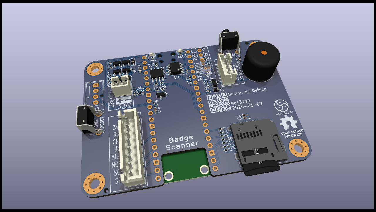
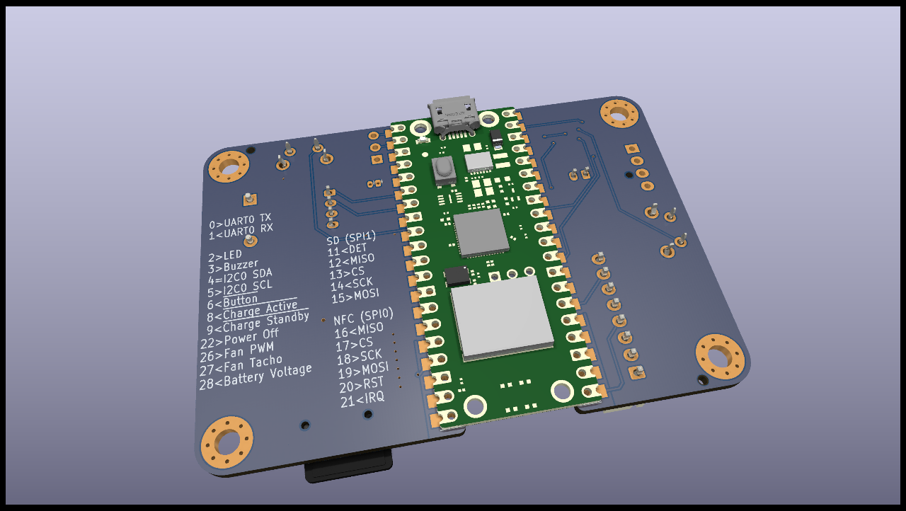
Raspberry Pi Pico W powered device to scan NFC-Badges and show a status on display
It is meant to be used with the widely available RFID-RC522 reader and the DFROBOT LCD1602 RGB Backlight Module but any other I2C Display should work as well.
The device features an I2C RTC with backup battery connector and an SD-Card reader connected via SPI for data storage.
There is also a buzzer that can be used for audible signals.
Power can be provided through the USB port of the Pico or through a LiPo battery connected to the board. The LiPo battery can also be charged via the USB port and the device will switch seamlessly between battery and usb power.
The button can be used to send a shutdown signal to the microcontroller which then can power the whole device off by pulling a GPIO low. Pressing the button while the device is off or pluggin in USB will power it up again.
| Qty | Value | Footprint | References |
|---|---|---|---|
| 7 | 3k3 | Resistor_SMD:R_0402_1005Metric | R7, R8, R9, R10, R11, R12, R13 |
| 6 | 100k | Resistor_SMD:R_0402_1005Metric | R6, R18, R20, R21, R23, R24 |
| 5 | 10k | Resistor_SMD:R_0402_1005Metric | R14, R15, R25, R26, R28 |
| 4 | 100n | Capacitor_SMD:C_0402_1005Metric | C1, C3, C5, C7 |
| 4 | 10u | Capacitor_SMD:C_0402_1005Metric | C2, C4, C6, C8 |
| 4 | 2k | Resistor_SMD:R_0402_1005Metric | R3, R4, R19, R27 |
| 4 | AO3400A | Package_TO_SOT_SMD:SOT-23 | Q1, Q5, Q6, Q8 |
| 3 | AO3401A | Package_TO_SOT_SMD:SOT-23 | Q2, Q3, Q7 |
| 2 | 1M | Resistor_SMD:R_0402_1005Metric | R16, R17 |
| 2 | 1N5819WS | Diode_SMD:D_SOD-323 | D3, D4 |
| 2 | 22u | Capacitor_SMD:C_0603_1608Metric | C9, C10 |
| 2 | 680R | Resistor_SMD:R_0402_1005Metric | R1, R2 |
| 1 | 100R | Resistor_SMD:R_0402_1005Metric | R5 |
| 1 | 18650 | Connector_JST:JST_PH_B2B-PH-K_1x02_P2.00mm_Vertical | BT2 |
| 1 | 1k | Resistor_SMD:R_0402_1005Metric | R22 |
| 1 | Activity | LED_SMD:LED_0603_1608Metric | D2 |
| 1 | Battery_Cell | Connector_Molex:Molex_PicoBlade_53047-0210_1x02_P1.25mm_Vertical | BT1 |
| 1 | Buzzer | Buzzer_Beeper:Buzzer_12x9.5RM7.6 | BZ1 |
| 1 | CJ431 | Package_TO_SOT_SMD:SOT-23 | U4 |
| 1 | DS3231MZ | Package_SO:SOIC-8_3.9x4.9mm_P1.27mm | U2 |
| 1 | Fan | Connector:FanPinHeader_1x04_P2.54mm_Vertical | M1 |
| 1 | I2C | Connector_JST:JST_PH_B4B-PH-K_1x04_P2.00mm_Vertical | J3 |
| 1 | LOGO | My_Footprints:CutieMark5mmInverted | G*** |
| 1 | LOGO | My_Footprints:qr_qete.sh-el_08 | G*** |
| 1 | Micro_SD_Card_Det1 | My_Footprints:TF_PUSH_Micro-SD-Connector | J4 |
| 1 | NFC-Module | Connector_JST:JST_XH_B8B-XH-A_1x08_P2.50mm_Vertical | J1 |
| 1 | Pico W | Badge-Scanner:RPi_PicoW_SMD_TH_NoSilkscreenText | U1 |
| 1 | Power | Button_Switch_THT:SW_Tactile_SPST_Angled_PTS645Vx58-2LFS | SW1 |
| 1 | Power | LED_SMD:LED_0603_1608Metric | D1 |
| 1 | Reset | Button_Switch_THT:SW_Tactile_SPST_Angled_PTS645Vx31-2LFS | SW2 |
| 1 | Serial | Connector_PinHeader_2.54mm:PinHeader_1x03_P2.54mm_Vertical | J2 |
| 1 | TP4056 | Package_SO:HSOP-8-1EP_3.9x4.9mm_P1.27mm_EP2.41x3.1mm | U3 |
The 65 most common of 72 parts.
arcticlula/Netscore
Device that keeps track of a volleyball's game score (points and sets). Ideally it should be mounted on the net, since it has a display on the front and back and buttons on the sides.


Qeteshpony/AC-Controller
Universal WiFi-Based remote control for IoT Devices

STB1019/BLINDO2.0
Blindo is an open source project made by the members of IEEE Student Branch 1019 from Brescia University (Università degli Studi di Brescia) in collaboration with the organization (Informatici Senza…


It measures 73 × 52 mm and has 2 copper layers, 1.6 mm thick.
72 parts, built around the CJ431, DS3231MZ/V+, TP4056 and AO3400A. The full list of its parts is on this page, with links to each part's symbol and footprint where PCBKit's library has them.
From the Qeteshpony/Badge-Scanner repository on GitHub, at the commit this page was made from: the board is pcb/Badge-Scanner.kicad_pcb and its schematic pcb/Badge-Scanner.kicad_sch. PCBKit opens the board in the browser, with nothing to install.
Its repository publishes it under the BSD-2-Clause licence: you may reuse it on that licence's terms (keep the author's notice, and for a copyleft licence share your changes alike).