

2 layers216 × 90 mm
LKP Chu Electrode Tile
Project-Alpaca/LKP
🍌🎹 Capacitive touch slider controller for rhythm games.
20 parts21
 Project-Alpaca/LKP21
🍌🎹 Capacitive touch slider controller for rhythm games.
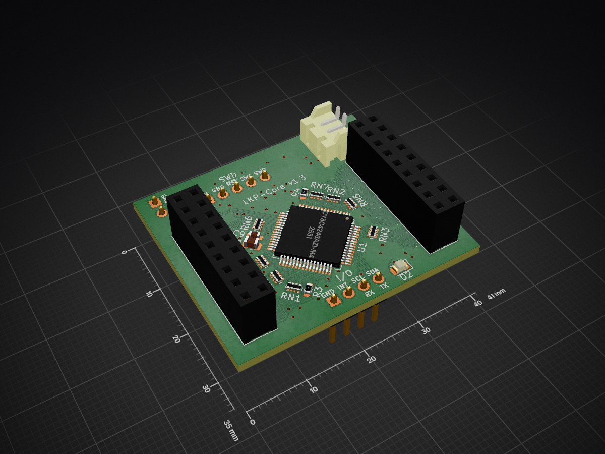
LKP Core is an open-source printed circuit board by Project-Alpaca, from the Project-Alpaca/LKP repository on GitHub. It is a 2-layer board of 41 × 35 mm with 34 parts on 93 nets, routed with 399 tracks and 51 vias.
It is built around the CY8C4246AZI-M445 and MBR0520L. Its parts include 12 capacitors, 6 connectors, 4 resistors, 2 diodes and 1 IC. It belongs with the sensors and measurement boards of this library.

レンくんピアノ (Len-kun Piano)
Capacitive touch slider controller for rhythm games.
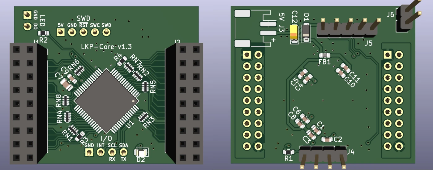
Microcontroller board for use with LKP electrode boards. Supports up to 32 channel of self capacitance input. Includes a WS281x LED driver channel with protection resistor. Supports I2C or UART as communication methods.
For sample firmware for use with LKP-Core, see LKP-FW.
I/O port:
| # | Description |
|---|---|
| 1 | GND |
| 2 | INT |
| 3 | SCL/RX |
| 4 | SDA/TX |
WS281x LED connector:
| # | Description |
|---|---|
| 1 | GND |
| 2 | LED |
SWD connector:
| # | Description |
|---|---|
| 1 | VTARG |
| 2 | GND |
| 3 | RESET |
| 4 | SWCLK |
| 5 | SWDIO |
IMPORTANT: WS281x LED driver will not work on this variant. See errata. This variant is only included for documentation purposes and will no longer receive updates.
A variant of LKP-Core that originally focused on improved accessibility for arcade controller DIY hobbyists with only basic (through hole) soldering skills. All parts used in this variant (once the chip shortage situations improve) are available for use with JLCPCB Assembly service, thus enables the possibility of ordering fully assembled and working boards straight from JLCPCB. Even without the assembly service working at the moment, the chip used in this variant can be purchased from LCSC in low quantity for a lot less money compare to the original chip on Digi-key, so it also acts as a budget option without sacrificing performance in significant ways.
Electrode board for Project DIVA Future Tone slider controller. Works as a 2-tile setup. Both tiles use the same design, with right tile being a 180 degree rotated version of the left tile.
Electrode board for Chunithm slider controller. Works the same as its LKP-Diva counterpart.
I2C quick connect (compatible with SparkFun Qwiic® and Adafruit STEMMA® QT) interface for LKP-Core. Goes up to 1MHz for I2C connections and up to 24MHz for UART connections. Converts between 5V logic used by LKP-Core and 3.3V logic used by Qwiic®/STEMMA® QT.
It is also possible to use it to convert UART signal for main microcontroller running between 1.65V and 3.6V. To set it up:
Note that although the low side of the level shifter can take any voltage between 1.65V and 3.6V, 3.3V must be used in order to maintain compatibility with other Qwiic®/STEMMA® QT-compatible systems.
CC0603KRX5R8BB105)CL10B104KA8NNNC)GRM2195C1H103JA01D.GCM1885C1H222JA16D.MBR0520L).LKP-IF-*).LKP-IF-*).4D02WGJ0561TCE).CY8C4246AZI-M445 (or CY8C4247AZI-M485, Needs minor firmware modifications).CL10B104KA8NNNC).MBR0520L).TCA9406DCTR.By default LKP expects 5V power. Using lower supply voltage down to 1.8V is possible by modifying the power specs in LKP-FW and adding a level shifter module to the WS281x driver pin (labeled as LED on board). Reference voltage for I/O can be approximated by tapping into the VTARG pin on the SWD port.
| Qty | Value | Footprint | References |
|---|---|---|---|
| 8 | 560 | Resistor_SMD:R_Array_Convex_4x0402 | RN1, RN2, RN3, RN4, RN5, RN6, RN7, RN8 |
| 5 | 1uF | Capacitor_SMD:C_0603_1608Metric | C2, C3, C5, C8, C11 |
| 4 | 0.1uF | Capacitor_SMD:C_0603_1608Metric | C1, C4, C6, C10 |
| 2 | 560 | Resistor_SMD:R_0603_1608Metric | R3, R4 |
| 1 | 10nF C0G | Capacitor_SMD:C_0805_2012Metric | C7 |
| 1 | 10uF | Capacitor_Tantalum_SMD:CP_EIA-3216-18_Kemet-A | C12 |
| 1 | 1k | Resistor_SMD:R_0603_1608Metric | R1 |
| 1 | 2.2nF C0G | Capacitor_SMD:C_0603_1608Metric | C9 |
| 1 | 330Ohm@100MHz | Inductor_SMD:L_0603_1608Metric | FB1 |
| 1 | 470 | Resistor_SMD:R_0603_1608Metric | R2 |
| 1 | CY8C4246AZI-M445 | Package_QFP:TQFP-64_10x10mm_P0.5mm | U1 |
| 1 | IO | Connector_PinHeader_2.54mm:PinHeader_1x04_P2.54mm_Vertical | J4 |
| 1 | Intercon L | Connector_PinSocket_2.54mm:PinSocket_2x09_P2.54mm_Vertical | J1 |
| 1 | Intercon R | Connector_PinSocket_2.54mm:PinSocket_2x09_P2.54mm_Vertical | J2 |
| 1 | MBR0520L | Diode_SMD:D_SOD-123 | D1 |
| 1 | Power JST PH | Connector_JST:JST_PH_S2B-PH-SM4-TB_1x02-1MP_P2.00mm_Horizontal | J3 |
| 1 | SWD | Connector_PinHeader_2.54mm:PinHeader_1x05_P2.54mm_Vertical | J5 |
| 1 | WS281x | Connector_PinHeader_2.54mm:PinHeader_1x02_P2.54mm_Vertical | J6 |
| 1 | Yellow | LED_SMD:LED_0805_2012Metric | D2 |
Project-Alpaca/LKP
🍌🎹 Capacitive touch slider controller for rhythm games.

Project-Alpaca/LKP
🍌🎹 Capacitive touch slider controller for rhythm games.


batterylabunipi/TWIST
TWIST is an open framework for Li-ion cell characterization based on Python and Raspberry Pi

voloviq/maithoga_lcd_board_480x320_R61529
PCB Board for Maithoga display with resolution 480x320 based on chip R61529 compatible with ILI9481.

Sagaz0501/esp32-drone
PCB ESP32 quadcopter: KiCad hardware + Madgwick IMU firmware + WiFi web UI


ananevego/ProjectFreeCad
Конвертер библиотечных footprint-файлов KiCad .kicadmod в самостоятельные библиотеки FreePCB2 .fpl. Написан на Python 3.10+, внешние зависимости не нужны.


It measures 41 × 35 mm and has 2 copper layers, 1.6 mm thick.
34 parts, built around the CY8C4246AZI-M445 and MBR0520L. The full list of its parts is on this page, with links to each part's symbol and footprint where PCBKit's library has them.
From the Project-Alpaca/LKP repository on GitHub, at the commit this page was made from: the board is pcb/LKP-Core/LKP-Core.kicad_pcb and its schematic pcb/LKP-Chu-Electrode-Tile/LKP-Chu-Electrode-Tile.kicad_sch. PCBKit opens the board in the browser, with nothing to install.
Its repository states no licence, so its author keeps all rights: ask Project-Alpaca before reusing the design.