2 layers65 × 30 mm
Rgb to hdmi
hoglet67/RGBtoHDMI
Bare-metal Raspberry Pi project that provides pixel-perfect sampling of Retro Computer RGB/YUV video and conversion to HDMI
33 parts1kGPL-3.0

 PinBus/high-voltage_driver_board1
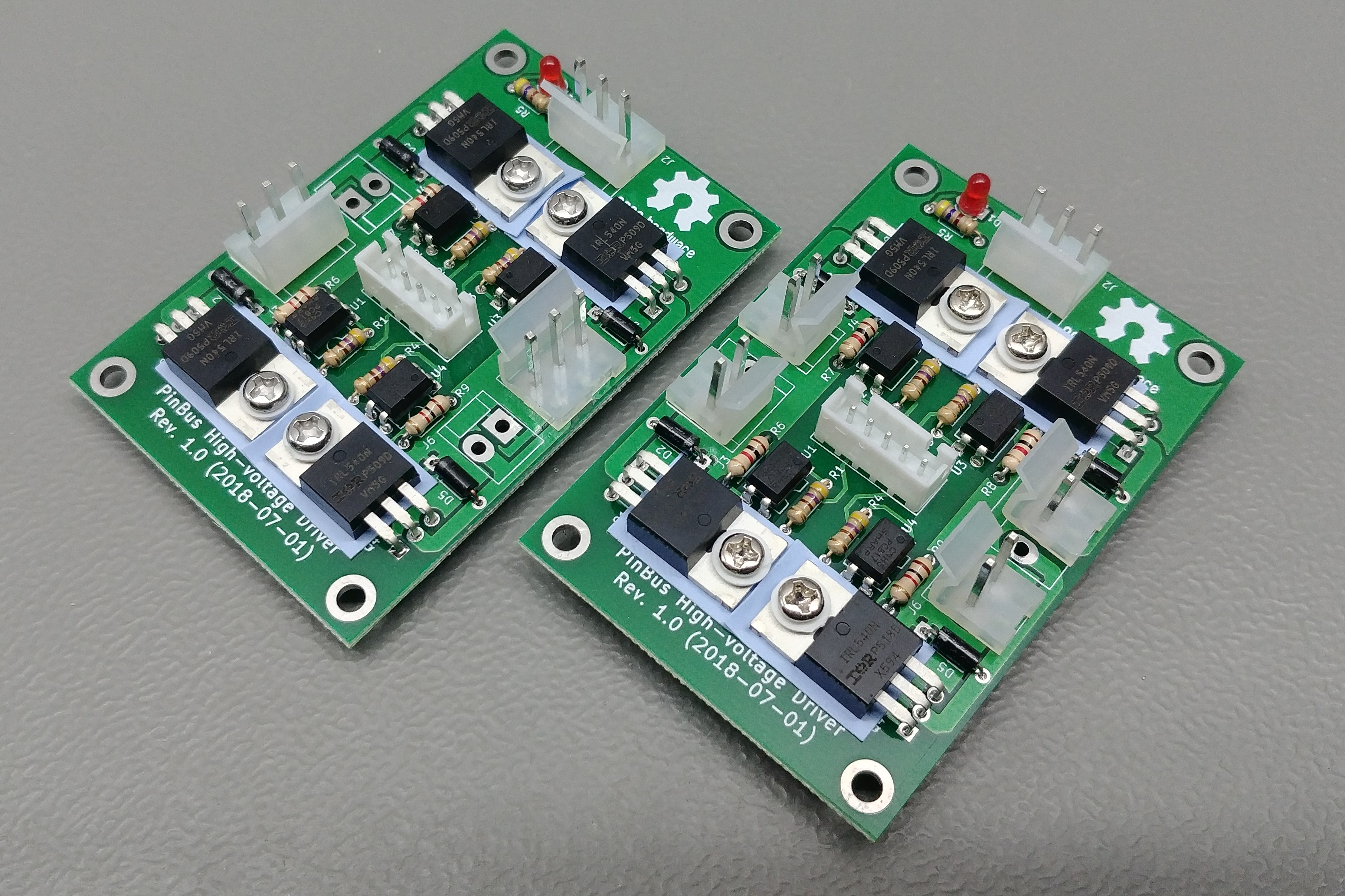
This board has four independant high voltage drivers. These boards were designed to drive pinball machine solenoids, but their use is not limited to pinball machines.
High voltage driver V1.0 is an open-source printed circuit board by PinBus, from the PinBus/high-voltage_driver_board repository on GitHub, published under the GPL-3.0 licence. It is a 2-layer board of 75 × 50 mm with 33 parts on 21 nets, routed with 130 tracks and 0 vias.
Its parts include 9 resistors, 6 connectors, 5 diodes, 4 ICs and 4 transistors.
This board has four independant high voltage drivers. These boards were designed to drive pinball machine solenoids, but their use is not limited to pinball machines. These boards can als be used to drive high power LEDs, DC motors, etc... As long as the used IRL540 MOSFETs are able to provide enough power to the device being driven. The MOSFETs are driven by the PC817 opto-couplers, so the digital inputs are isolated from the high-power section.
The outputs can be configured in two ways. Every output can be exposed by a separate 2-pin connector, or two outputs can be joined together into a 3-pin connector. This is useful for flipper solenoids.
Pin 1 (marked by the square footprint) on J1 is the common ground pin. Pin 1 on jumper J2 is +5V, pin 2 is ground, and pin 3 is +25V to max. +75V.
Warning: These designs are made as part of a hobby project and thus come with no guarantees. Do not use these designs in for any critical systems! Working with voltages higher than +40V can be potentially dangerous, please take appropriate safety measures!
| Identifiers | Quantity | Part |
|---|---|---|
| D1 | 1x | 5mm red LED |
| D2 - D5 | 4x | 1N4004 compatible diode |
| J1 | 1x | JST XH connector, 2.5mm pitch, 5-way, through-hole |
| J2 | 1x | CH 3.96 connector, 3-way, through hole |
| J3 - J6 | CH 3.96 connector, 2x 3-way or 4x 2-way, through-hole | |
| Q1 - Q4 | 4x | IRL540 MOSFET |
| R1 - R4 | 4x | 51Ω 0.25W resistor |
| R5 | 1x | 470Ω 0.25W resistor |
| R6 - R9 | 4x | 1kΩ 0.25W resistor |
| U1 - U4 | 4x | PC817 Sharp opto-coupler |
| Qty | Value | Footprint | References |
|---|---|---|---|
| 4 | 1K | Resistors_THT:R_Axial_DIN0204_L3.6mm_D1.6mm_P7.62mm_Horizontal | R6, R7, R8, R9 |
| 4 | 51R | Resistors_THT:R_Axial_DIN0204_L3.6mm_D1.6mm_P7.62mm_Horizontal | R1, R2, R3, R4 |
| 4 | D | Diodes_THT:D_DO-35_SOD27_P7.62mm_Horizontal | D2, D3, D4, D5 |
| 4 | PC817 | Housings_DIP:DIP-4_W7.62mm | U1, U2, U3, U4 |
| 4 | Q_NMOS_DSG | TO_SOT_Packages_THT:TO-220-3_Horizontal | Q1, Q2, Q3, Q4 |
| 3 | CONN_01X03 | Connectors_Molex:Molex_KK-41791-03_03x3.96mm_Straight | J2, J3, J5 |
| 2 | CONN_01X02 | Connectors_Molex:Molex_KK-41791-02_02x3.96mm_Straight | J4, J6 |
| 1 | 470 | Resistors_THT:R_Axial_DIN0204_L3.6mm_D1.6mm_P7.62mm_Horizontal | R5 |
| 1 | CONN_01X05 | Connectors_JST:JST_XH_B05B-XH-A_05x2.50mm_Straight | J1 |
| 1 | LED | LEDs:LED_D3.0mm | D1 |
The 28 most common of 33 parts.
hoglet67/RGBtoHDMI
Bare-metal Raspberry Pi project that provides pixel-perfect sampling of Retro Computer RGB/YUV video and conversion to HDMI

mntmn/amiga2000-gfxcard
MNT VA2000, an Open Source Amiga 2/3/4000 Graphics Card (Zorro II/III), written in Verilog

hackclub/OnBoard
💡 Join 1,000 teenagers and make your first PCB with a $100 grant!

Arrow-air/project-quiver
Project Quiver documentation, designs, and project artifacts.

ozel/DIY_particle_detector
A mobile low-cost spectrometer for measuring radioactivity and the energy of ionising radiation like alpha particles and electrons

BlueAndi/Pixelix
Full RGB LED matrix, based on an ESP32 and WS2812B LEDs or emulated LEDs on TFT.

jrsteensen/OpenHornet
OpenHornet 1:1 F/A-18C Simulator Repository

It measures 75 × 50 mm and has 2 copper layers, 1.6 mm thick.
33 parts. The full list of its parts is on this page, with links to each part's symbol and footprint where PCBKit's library has them.
From the PinBus/high-voltage_driver_board repository on GitHub, at the commit this page was made from: the board is high-voltage_driver_V1.0.kicad_pcb. PCBKit opens the board in the browser, with nothing to install.
Its repository publishes it under the GPL-3.0 licence: you may reuse it on that licence's terms (keep the author's notice, and for a copyleft licence share your changes alike).