2 layers57.3 × 19 mm

 Pimentoso/Paddino0215
Small and simple mechanical gamepad/macropad.
Tutorial is an open-source printed circuit board by Pimentoso, from the Pimentoso/Paddino02 repository on GitHub, published under the GPL-3.0 licence. It is a 2-layer board of 95.3 × 71.4 mm with 26 parts on 34 nets, routed with 152 tracks and 0 vias.
It belongs with the keyboards and input boards and the AVR (ATmega, ATtiny) boards of this library.
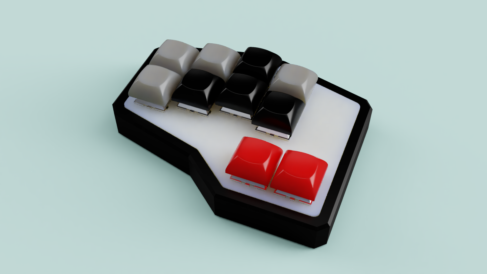
10-keys DIY mechanical macropad/gamepad. Features staggered columns, 2 thumb keys, symmetric PCB (you can build right-handed and left-handed versions with the same PCB). Intended to use with QMK firmware.
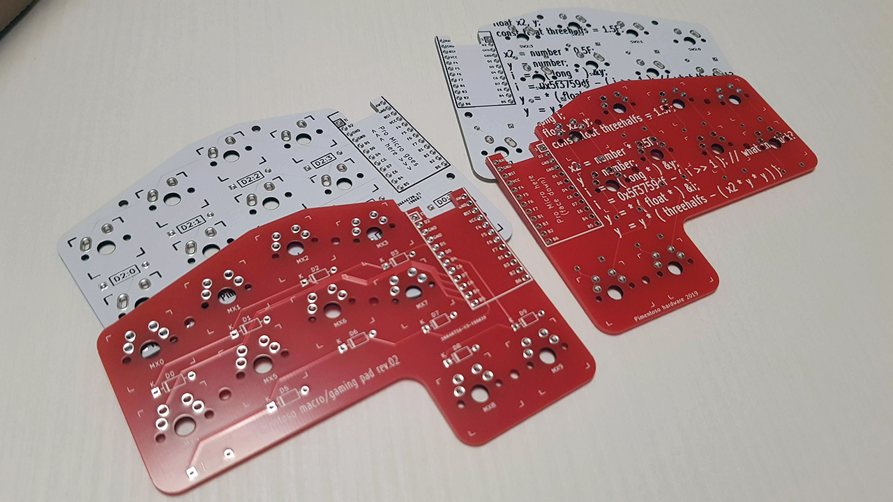 Some PCBs. The white ones are from the first revision, they're just in the pic for show.
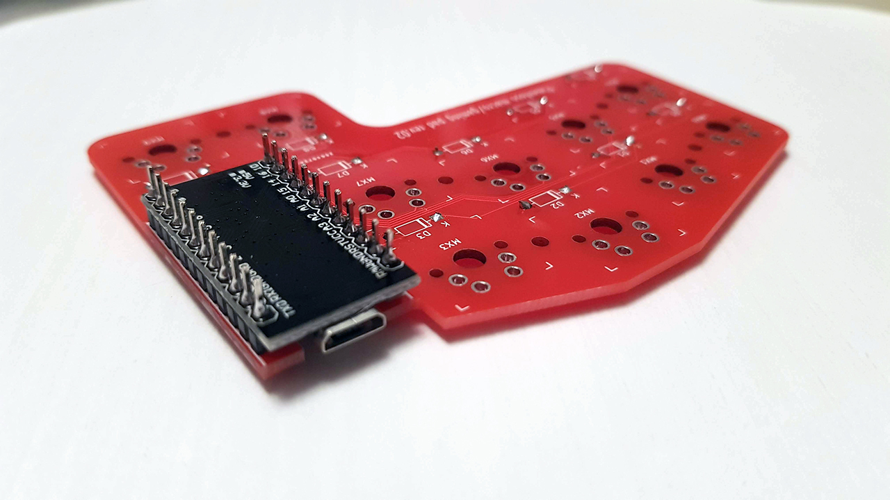 Pro Micro soldered with header pins. The pins are too long and need to be snipped.
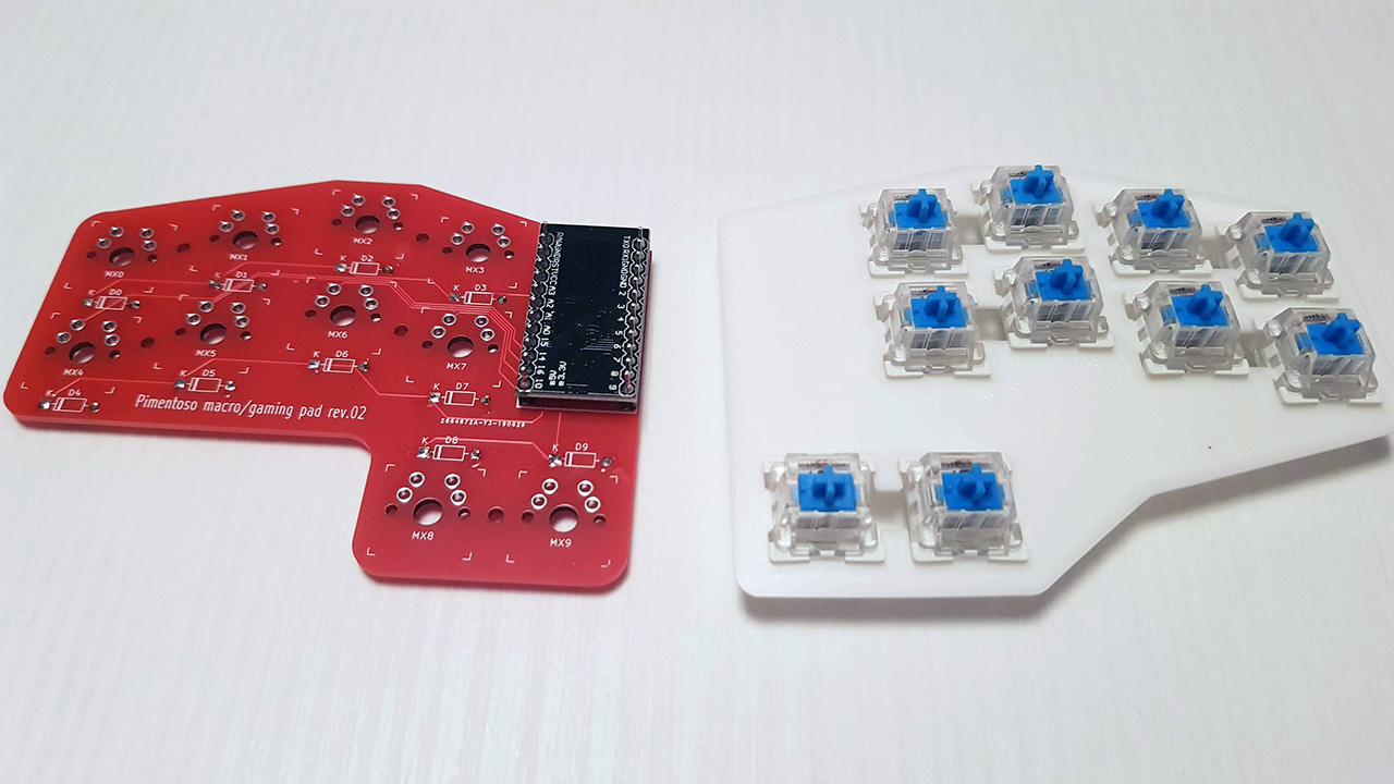 Plate with blue switches snapped in place.
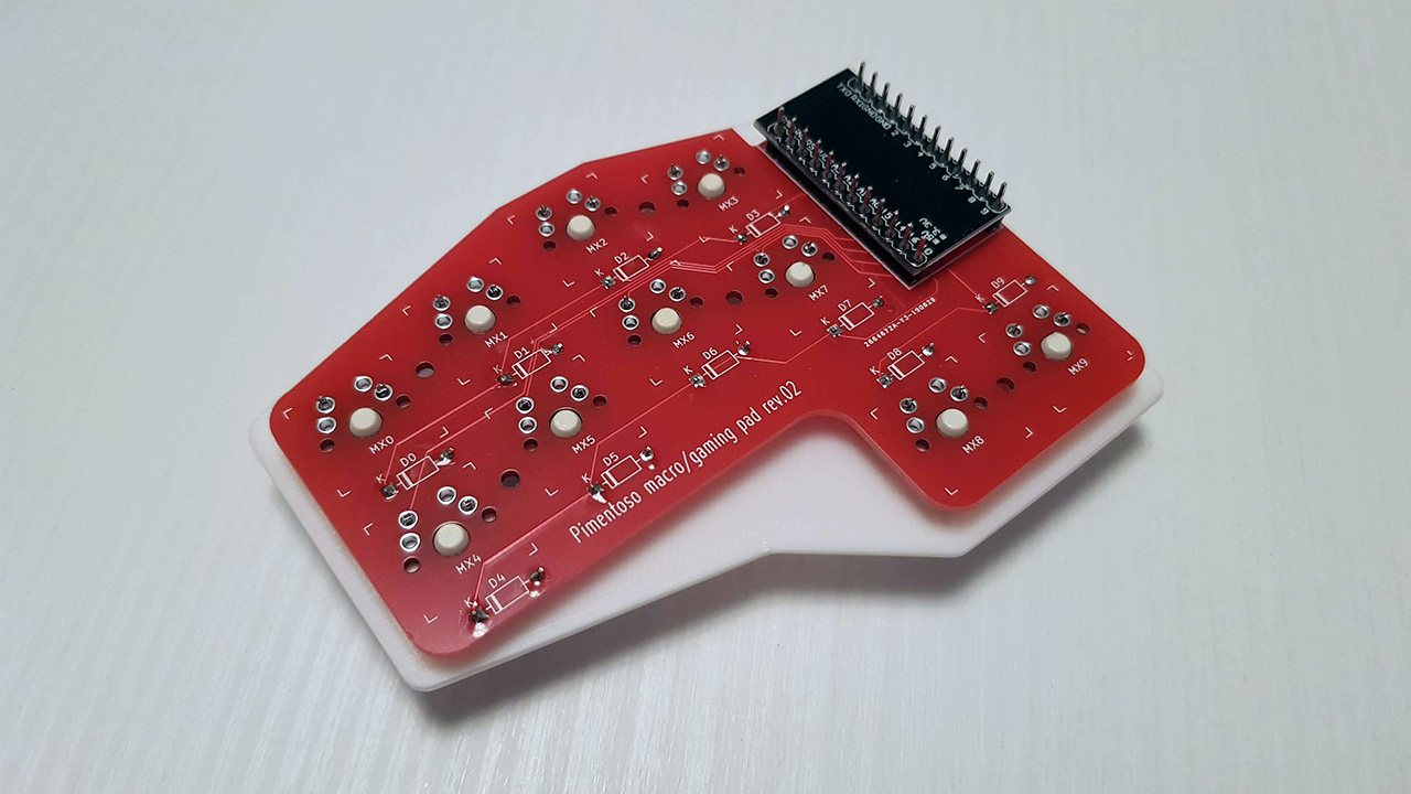 PCB joined with plate.
 Right and left versions.
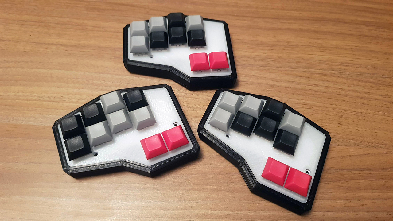 Finished pads (first revision)
 Finished pad (second revision). Compared to the first revision, the screw holes are hidden between the switches.
The firmware folder contains the keymap .json files and firmware .hex files for both the right and left handed versions.
The provided keymap files are very basic, and the second layer is empty. So some customization is recommended.
To edit the keys, you have to load the .json file into https://kbfirmware.com/, configure the keys as you like, and compile a .hex file directly from the site. You can then flash the .hex file on the pad using avrdude.
The easiest way is to install QMK Toolbox
Connect your pad to USB, enter programming mode, select the .hex file into QMK Toolbox, and flash.
To enter programming mode, use the hole on the bottom of the case. You can stick a bent clip/screwdriver into it to short the RESET and GROUND pins of the Pro Micro. (There are actually 2 holes, because in the right-handed version the Pro Micro is flipped and the pins are on the other side)
Head over to https://jlcpcb.com/quote and upload the gerber.zip file, located inside the kicad/gerber folder. The default options are good (you can change the color for swag). Just make sure PCB Thickness is set to 1.6.
Since the PCB is smaller than 100mm, the cost will be $2 for 5 of them, and shipping will be free if it's your first order.
This project is licensed under the GPLv3 License - see the LICENSE.md file for details
| Qty | Value | Footprint | References |
|---|---|---|---|
| 10 | 1N4148 | Diode_THT:D_DO-35_SOD27_P7.62mm_Horizontal | D0, D1, D2, D3, D4, D5, D6, D7, D8, D9 |
| 10 | MX-NoLED | keyswitches:MX_reversible | MX0, MX1, MX2, MX3, MX4, MX5, MX6, MX7, MX8, MX9 |
| 5 | MountingHole | MountingHole:MountingHole_2.2mm_M2 | H0, H1, H2, H3, H4 |
| 1 | ProMicro | keebio:ArduinoProMicro | ProMicro1 |

hackclub/OnBoard
💡 Join 1,000 teenagers and make your first PCB with a $100 grant!


harbaum/galagino
A Galaga, Pac-Man and Donkey Kong arcade emulator for the ESP32

Luos-io/luos_engine
Open-source and real-time orchestrator for cyber-physical-systems, to easily design, test and deploy embedded applications and digital twins.

google/walt
A device for measuring latency of physical sensors and outputs on phones and computers

It measures 95.3 × 71.4 mm and has 2 copper layers, 1.6 mm thick.
26 parts. The full list of its parts is on this page, with links to each part's symbol and footprint where PCBKit's library has them.
From the Pimentoso/Paddino02 repository on GitHub, at the commit this page was made from: the board is kicad/tutorial.kicad_pcb. PCBKit opens the board in the browser, with nothing to install.
Its repository publishes it under the GPL-3.0 licence: you may reuse it on that licence's terms (keep the author's notice, and for a copyleft licence share your changes alike).