
2 layers81.3 × 96.5 mm

 PanZolw/PiLaser
So, this is it—PicoLaser. It’s basically my way of flipping the bird to the massive wallet-drain that usually comes with laser hobbyism.
Galwo is an open-source printed circuit board by PanZolw, from the PanZolw/PiLaser repository on GitHub. It is a 2-layer board of 208 × 196 mm with 24 parts on 51 nets, routed with 217 tracks and 3 vias.
It is built around the MCP4922-E/P. Its parts include 8 connectors, 3 capacitors, 3 resistors, 3 transistors and 2 ICs. It belongs with the RP2040 boards of this library.
So, this is it—PicoLaser. It’s basically my way of flipping the bird to the massive wallet-drain that usually comes with laser hobbyism. If you’ve ever looked into buying a commercial ILDA controller, you know the drill: proprietary junk, ancient software, and price tags that make you want to go lie down. I wanted something better. I wanted a wireless, scrappy, open-source "shield" for the Raspberry Pi Pico W that could actually hold its own against the big guys without requiring a small loan.
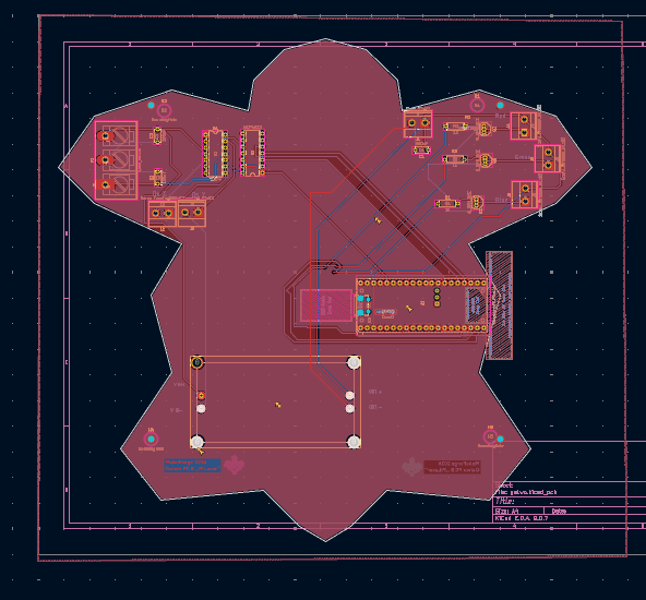
Commercial systems are usually black boxes. You plug them in, they work (hopefully), and you have zero clue what’s happening under the hood. PicoLaser changes that. By leaning on the dual-core RP2040, I’ve managed to get rock-solid, real-time vector control. No OS lag, no weird Linux jitters—just clean lines.
And yeah, it’s shaped like a turtle. Why? Because I’m "PanZolw," and because the world needs more hardware that doesn't just look like a boring green rectangle.
I swapped the beefy Pi 4 for a Raspberry Pi Pico W. To be honest, it was the best move I made. Running a laser on a full OS is overkill; it's like using a chainsaw to cut butter. The Pico W handles the WiFi data stream and the high-speed SPI communication simultaneously without breaking a sweat. Six bucks for the brain of a laser projector? I almost feel like I'm stealing.
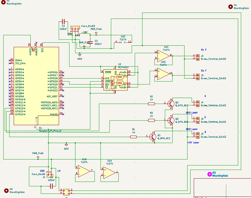
Instead of expensive analog modulation (which is great, don't get me wrong, but it’s pricey), I went with TTL control. By using some fast NPN transistors—good old 2N2222s—I can toggle the Red, Green, and Blue diodes on and off at light speed. You don't get subtle sunset fades, but you do get seven punchy, vibrant colors. For 90% of vector art and logos? It’s more than enough.
Powering this thing is a bit of a juggling act, but I think I’ve got it nailed.
The lean, mean version. No secondary DACs, just pure efficiency and transistor-based switching.
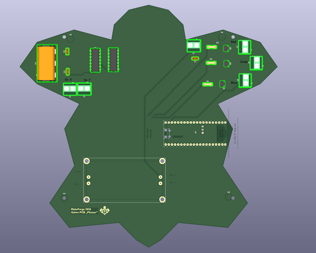
The final render. Matte Black solder mask, Gold (ENIG) finish, and that hexagonal shell pattern. I’m pretty proud of how the power and signal domains are separated—clean signals are happy signals.
I’ve put together a full Bill of Materials (BOM) in the root directory. If you’re smart about where you buy your parts, you can build this whole rig for under $150. View the BOM here
This project is open-source hardware. Build it, mod it, just don't be a jerk about it.
| Qty | Value | Footprint | References |
|---|---|---|---|
| 5 | Screw_Terminal_01x02 | TerminalBlock_Phoenix:TerminalBlock_Phoenix_MKDS-1,5-2-5.08_1x02_P5.08mm_Horizontal | J2, J3, J4, J5, J6 |
| 4 | MountingHole | MountingHole:MountingHole_2.7mm_M2.5 | H1, H2, H3, H4 |
| 3 | 100nF | Capacitor_THT:C_Disc_D5.0mm_W2.5mm_P5.00mm | C1, C2, C3 |
| 3 | 1k | Resistor_THT:R_Axial_DIN0207_L6.3mm_D2.5mm_P7.62mm_Horizontal | R1, R2, R3 |
| 3 | Q_NPN_BCE | Package_TO_SOT_THT:TO-92L_Inline | Q1, Q2, Q3 |
| 1 | Conn_01x02 | TerminalBlock_Phoenix:TerminalBlock_Phoenix_MKDS-1,5-2-5.08_1x02_P5.08mm_Horizontal | J1 |
| 1 | Conn_01x03 | TerminalBlock_Ningbo-Kagnex:TerminalBlock_Ningbo-Kagnex_HB9500M_1x03_P9.5mm | P1 |
| 1 | Conn_02x02_Counter_Clockwise | proba:Bez_nazwy | J7 |
| 1 | MCP4922 | Package_DIP:DIP-14_W7.62mm | U2 |
| 1 | RaspberryPi_Pico_W | proba:RaspberryPi_Pico_W_SMD_HandSolder_tht | A1 |
| 1 | TL074 | Package_DIP:DIP-14_W7.62mm | U1 |

qu1j0t3/vector_gen
In first version of PCB there is a bug that leaves U6 Vss/Vdd pins floating and U5 Vdd floating:


Felan7/midiFox
The MidiFox is a small Eurorack Module, that takes a Midi-Signal via MicroUSB from a Computer and turns it into Eurorack usbale Note value, midi velocity and gate CV.


It measures 208 × 196 mm and has 2 copper layers, 1.6 mm thick.
24 parts, built around the MCP4922-E/P. The full list of its parts is on this page, with links to each part's symbol and footprint where PCBKit's library has them.
From the PanZolw/PiLaser repository on GitHub, at the commit this page was made from: the board is PCB/galwo.kicad_pcb and its schematic PCB/galwo.kicad_sch. PCBKit opens the board in the browser, with nothing to install.
Its repository states no licence, so its author keeps all rights: ask PanZolw before reusing the design.