2 layers200 × 150 mm

 PainfulDiodes/BeanBoardSPI2
Hardware SPI interface plugin module for BeanBoard
BeanBoardSPI is an open-source printed circuit board by PainfulDiodes, from the PainfulDiodes/BeanBoardSPI repository on GitHub, published under the MIT licence. It is a 4-layer board of 199.4 × 80 mm with 42 parts on 114 nets, routed with 532 tracks and 79 vias.
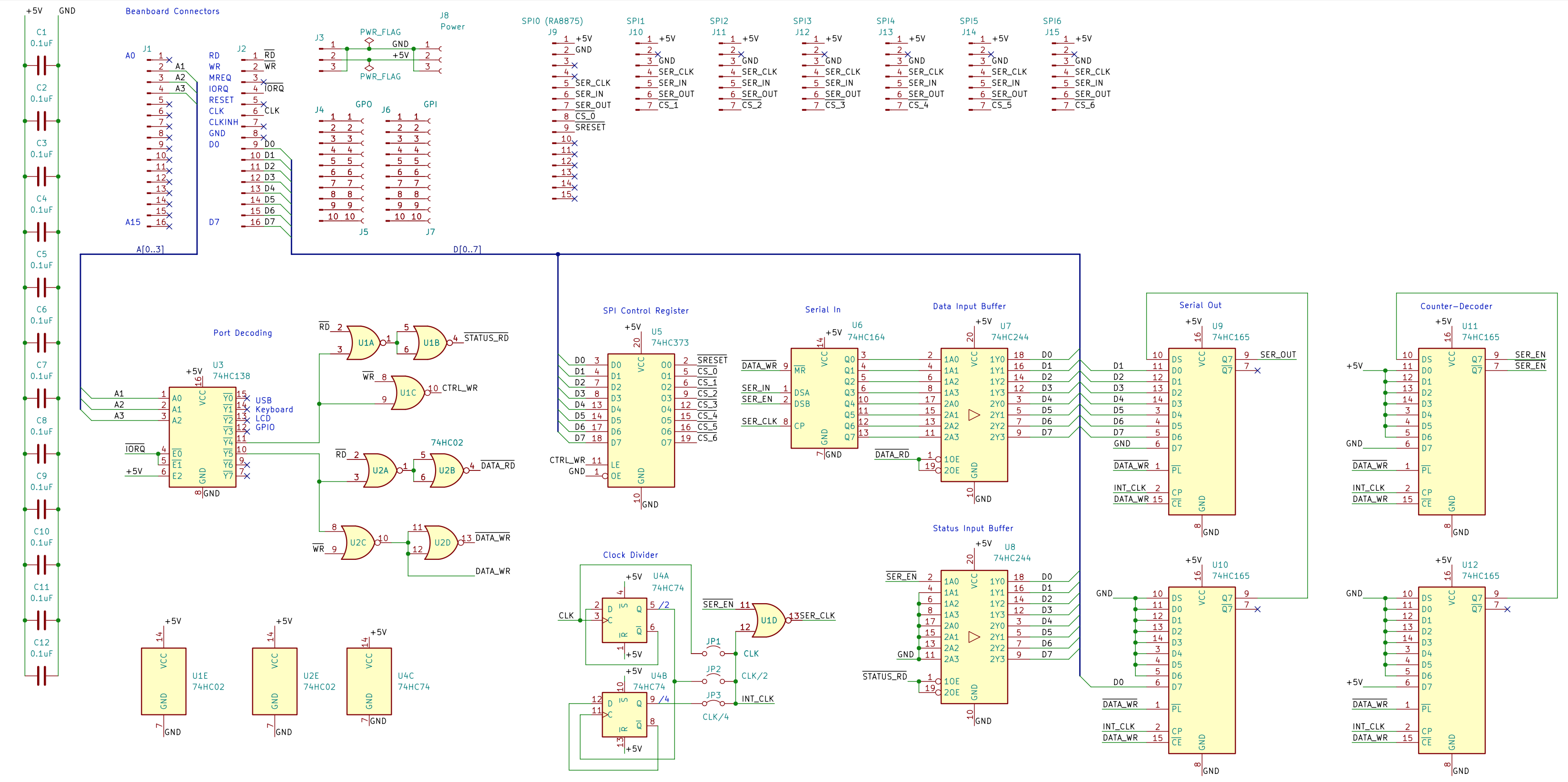
It is built around the 74HC244D, 74HC165D and 74HC02, with the 74HC138, 74HC164 and 74HC373D among its other parts. Its parts include 15 connectors, 12 capacitors and 12 ICs.


SPI controller in 74' logic for BeanBoard / BeanZee Z80 computer.
SPI is a fast serial interface commonly used for connecting microcontrollers to peripherals like SD cards, displays and sensors.
The intent of this design is to provide access to an RA8875 TFT panel controller and to flash memory modules on my Z80 homebrew computer. The Marvin monitor program provides software support for this configuration.
For background, please see the accompanying blog posts.
Thank you to those helpful folks at PCBWay who sponsored this build and provided the PCBs
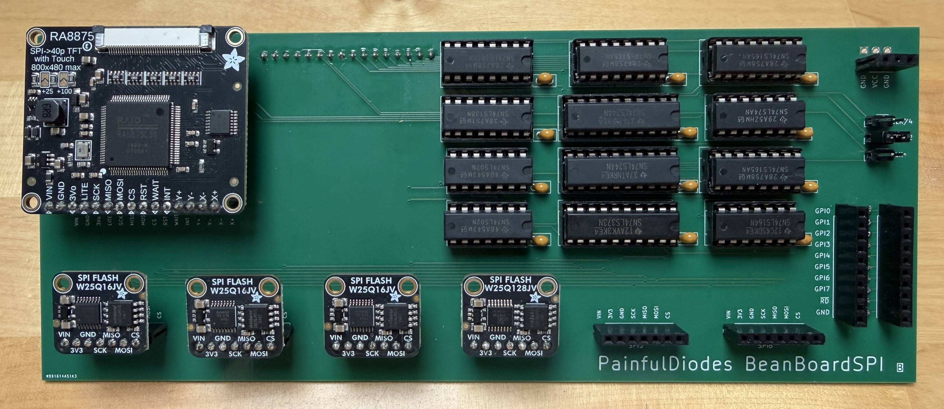 BeanBoardSPI Rev B populated with Adafruit SPI modules
 SPI timing
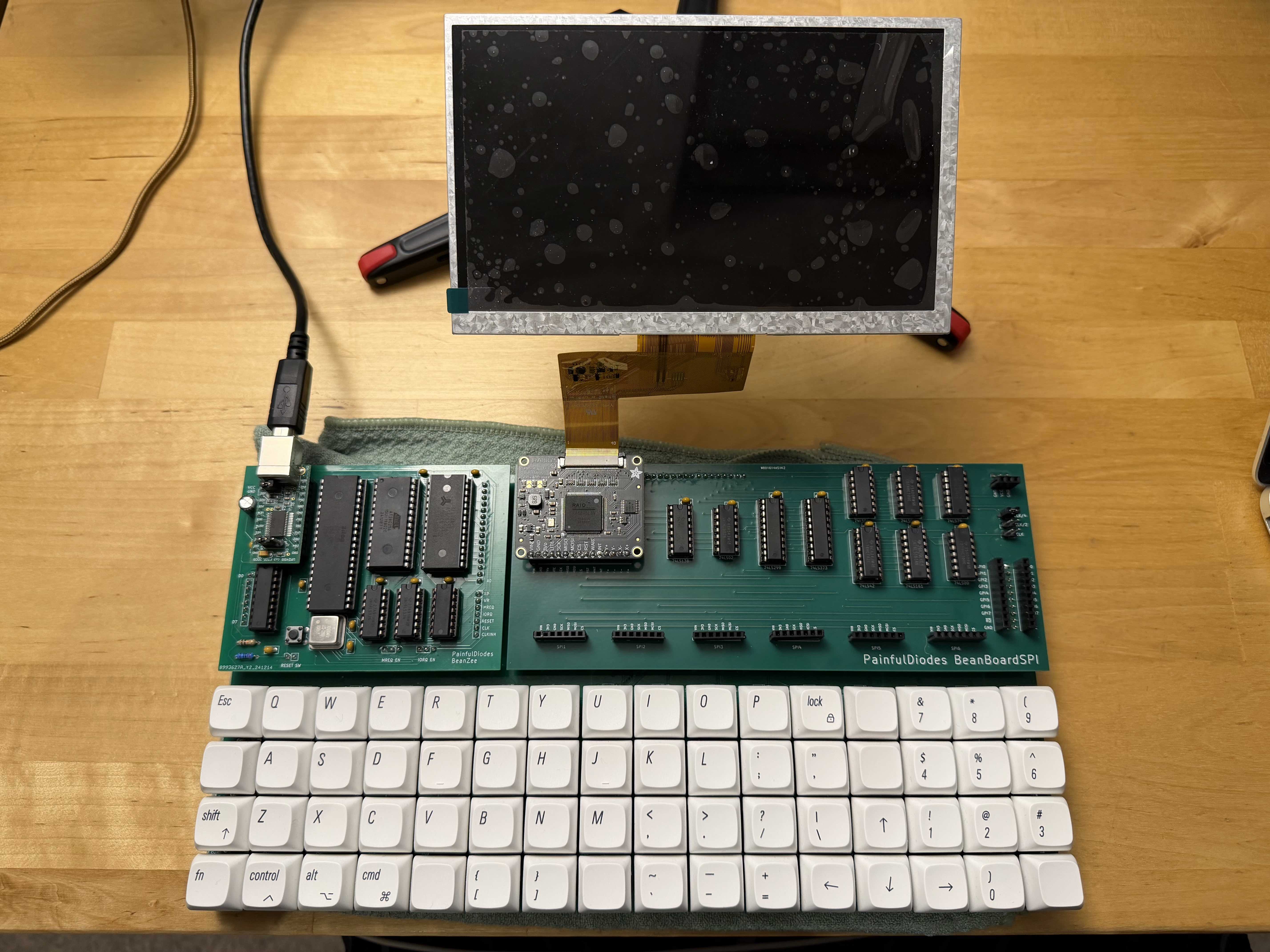 BeanBoardSPI Rev A Plugged into BeanBoard with BeanZee, and a TFT panel
| Qty | Value | Footprint | References |
|---|---|---|---|
| 12 | 0.1uF | Capacitor_THT:C_Disc_D5.0mm_W2.5mm_P2.50mm | C1, C2, C3, C4, C5, C6, C7, C8, C9, C10, C11, C12 |
| 4 | 74HC165 | Package_DIP:DIP-16_W7.62mm_Socket | U9, U10, U11, U12 |
| 2 | 74HC02 | Package_DIP:DIP-14_W7.62mm_Socket | U1, U2 |
| 2 | 74HC244 | Package_DIP:DIP-20_W7.62mm_Socket | U7, U8 |
| 2 | Conn_01x10_Pin | BeanBoardSPI:PinHeader_1x10_P2.54mm_Vertical | J4, J6 |
| 2 | Conn_01x16_Pin | BeanBoardSPI:PinHeader_1x16_P2.54mm_Vertical | J1, J2 |
| 1 | 74HC138 | Package_DIP:DIP-16_W7.62mm_Socket | U3 |
| 1 | 74HC164 | Package_DIP:DIP-14_W7.62mm_Socket | U6 |
| 1 | 74HC373 | Package_DIP:DIP-20_W7.62mm_Socket | U5 |
| 1 | 74HC74 | Package_DIP:DIP-14_W7.62mm_Socket | U4 |
| 1 | CLK | Connector_PinHeader_2.54mm:PinHeader_1x02_P2.54mm_Vertical | JP1 |
| 1 | CLK/2 | Connector_PinHeader_2.54mm:PinHeader_1x02_P2.54mm_Vertical | JP2 |
| 1 | CLK/4 | Connector_PinHeader_2.54mm:PinHeader_1x02_P2.54mm_Vertical | JP3 |
| 1 | Conn_01x03_Pin | BeanBoardSPI:PinHeader_1x03_P2.54mm_Vertical | J3 |
| 1 | GPI | Connector_PinSocket_2.54mm:PinSocket_1x10_P2.54mm_Vertical | J7 |
| 1 | GPO | Connector_PinSocket_2.54mm:PinSocket_1x10_P2.54mm_Vertical | J5 |
| 1 | Power | Connector_PinSocket_2.54mm:PinSocket_1x03_P2.54mm_Vertical | J8 |
| 1 | SPI0 (RA8875) | Connector_PinHeader_2.54mm:PinHeader_1x15_P2.54mm_Vertical | J9 |
| 1 | SPI1 | Connector_PinHeader_2.54mm:PinHeader_1x07_P2.54mm_Vertical | J10 |
| 1 | SPI2 | Connector_PinHeader_2.54mm:PinHeader_1x07_P2.54mm_Vertical | J11 |
| 1 | SPI3 | Connector_PinHeader_2.54mm:PinHeader_1x07_P2.54mm_Vertical | J12 |
| 1 | SPI4 | Connector_PinHeader_2.54mm:PinHeader_1x07_P2.54mm_Vertical | J13 |
| 1 | SPI5 | Connector_PinHeader_2.54mm:PinHeader_1x07_P2.54mm_Vertical | J14 |
| 1 | SPI6 | Connector_PinHeader_2.54mm:PinHeader_1x07_P2.54mm_Vertical | J15 |


snippyrow/-816-board
A retro computer motherboard for the W65C816S CPU. Dual-core expandable, 16mb extended memory, four expansion ports.

It measures 199.4 × 80 mm and has 4 copper layers, 1.6 mm thick.
42 parts, built around the 74HC244D, 74HC165D, 74HC02 and 74HC138. The full list of its parts is on this page, with links to each part's symbol and footprint where PCBKit's library has them.
From the PainfulDiodes/BeanBoardSPI repository on GitHub, at the commit this page was made from: the board is kicad/BeanBoardSPI.kicad_pcb and its schematic kicad/BeanBoardSPI.kicad_sch. PCBKit opens the board in the browser, with nothing to install.
Its repository publishes it under the MIT licence: you may reuse it on that licence's terms (keep the author's notice, and for a copyleft licence share your changes alike).