
2 layers98.4 × 93.8 mm

My first two layer PCB, spinning LED effect with no micro-controller or code.
Test1 is an open-source printed circuit board by PStinno, from the PStinno/led-spinner-pcb repository on GitHub, published under the CC-BY-SA-4.0 licence. It is a 2-layer board of 43.2 × 43.2 mm with 27 parts on 31 nets, routed with 275 tracks and 44 vias.
It is built around the 74AHC1G08GW and ICM7555N. Its parts include 16 diodes, 4 ICs, 3 resistors, 2 capacitors and 1 switch.


My first two layer PCB, spinning LED effect with no micro-controller or code.
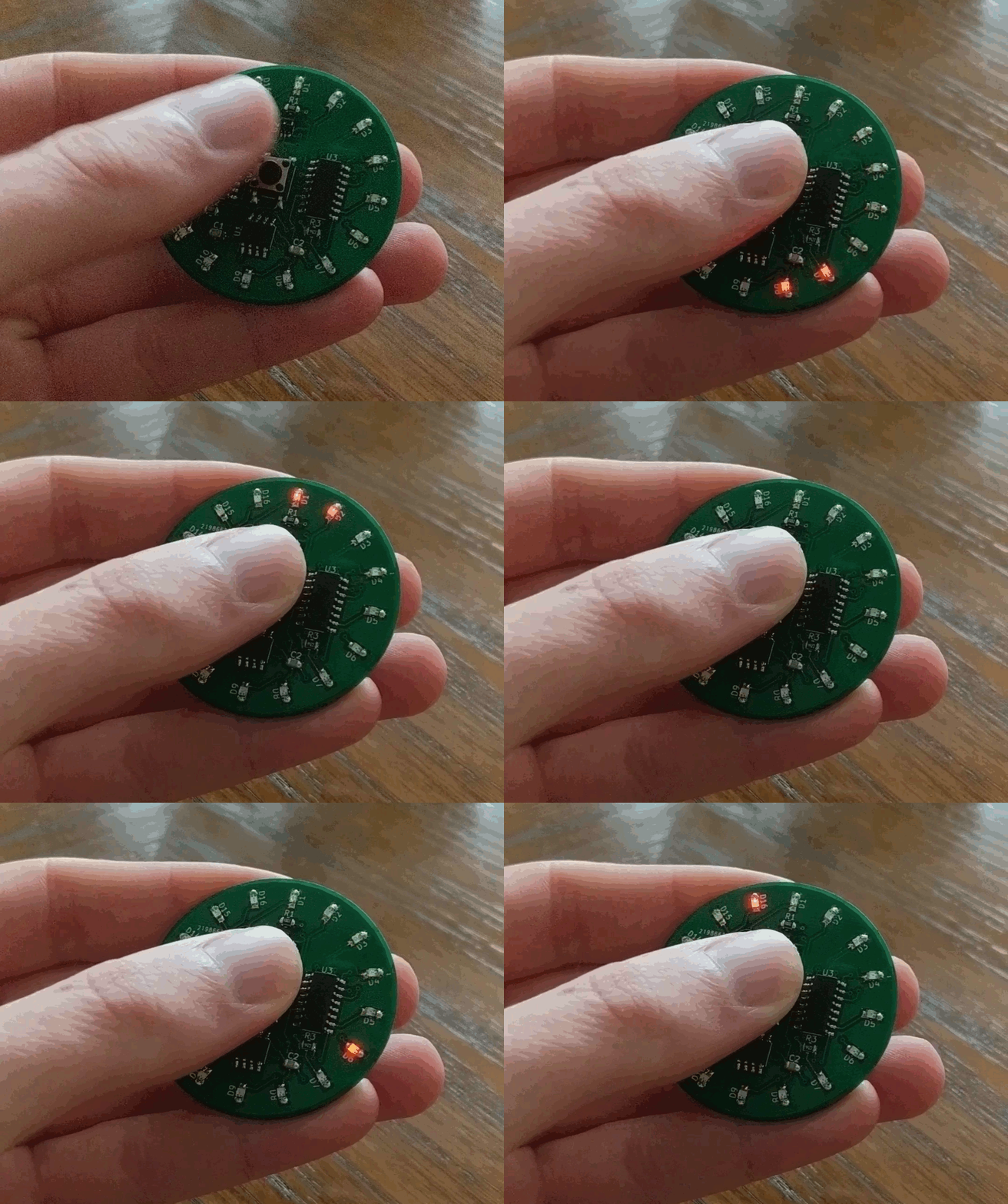
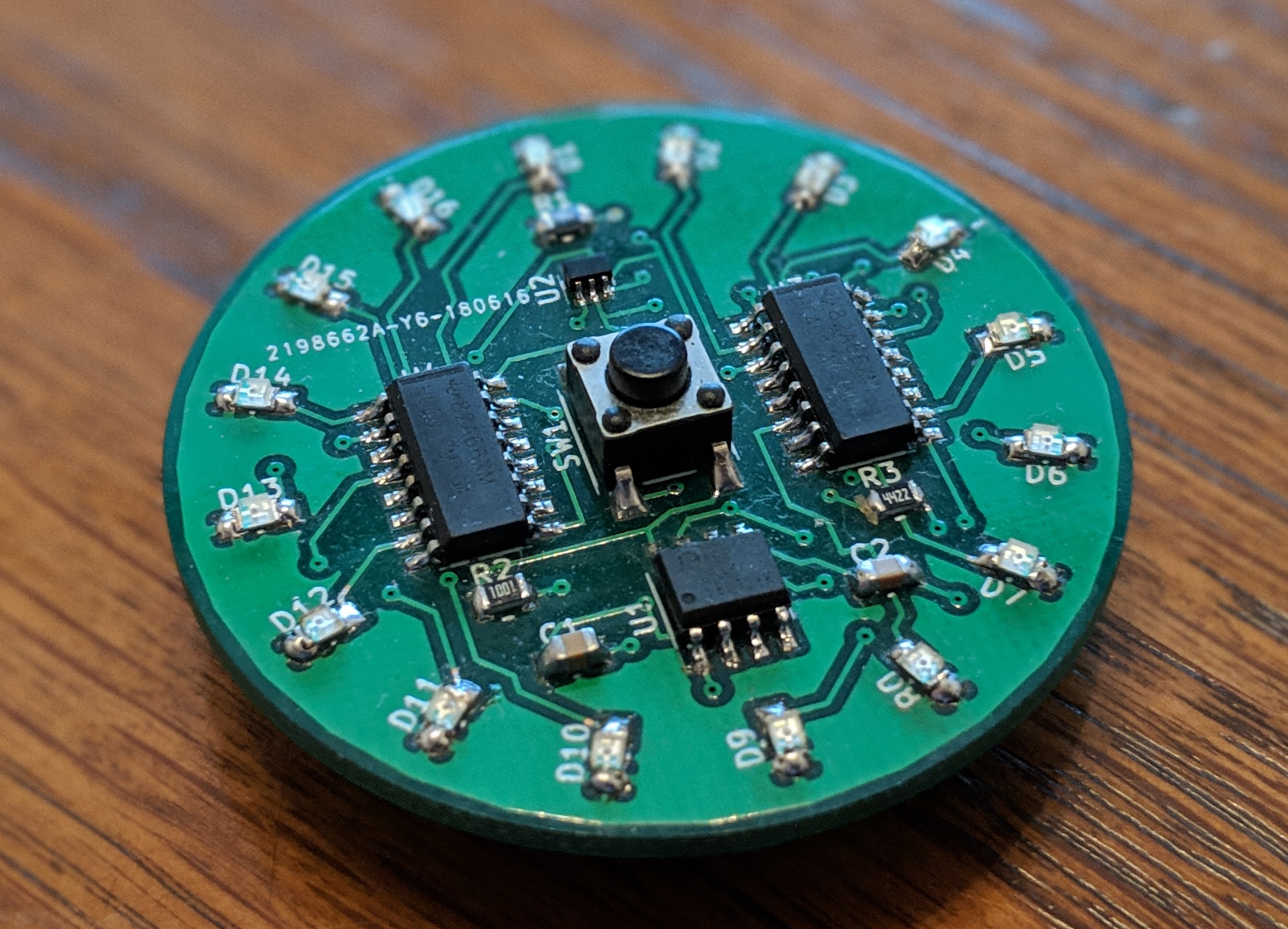
The circuit consists of two 4017 decade counters, connected together to create sixteen sequential outputs. The outputs progress on each clock cycle and loop back to the beginning when the end is reached. Each output is connected to an LED on the perimeter of the PCB. The clock input is connected to a 555 timer IC in an astable configuration. This generates a continous square wave, causing the progression of the outputs and the spinning effect. The momentary push button completes the circuit, so it is only powered when the button is held down.
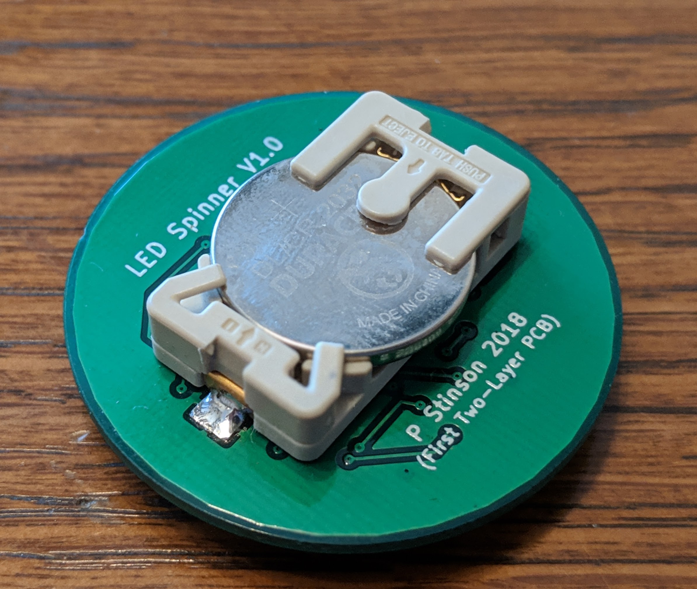

This work is licensed under a Creative Commons Attribution-ShareAlike 4.0 International License.
| Qty | Value | Footprint | References |
|---|---|---|---|
| 16 | LED | LEDs:LED_0805 | D1, D2, D3, D4, D5, D6, D7, D8, D9, D10, D11, D12, D13, D14, D15, D16 |
| 2 | 4017 | Housings_SOIC:SOIC-16_3.9x9.9mm_Pitch1.27mm | U3, U4 |
| 1 | 10nF | Capacitors_SMD:C_0805 | C2 |
| 1 | 1K | Resistors_SMD:R_0805 | R2 |
| 1 | 1uF | Capacitors_SMD:C_0805 | C1 |
| 1 | 68k | Resistors_SMD:R_0805 | R3 |
| 1 | 74AHC1G08 | TO_SOT_Packages_SMD:SOT-353_SC-70-5 | U2 |
| 1 | CR2032 3V | Coin_Cell_Holders:MPD_BA2032SM | BT1 |
| 1 | ICM7555 | Housings_SOIC:SOIC-8_3.9x4.9mm_Pitch1.27mm | U1 |
| 1 | R | Resistors_SMD:R_0805 | R1 |
| 1 | SW_Push | Buttons_Switches_SMD:SW_SPST_PTS645 | SW1 |

ALeggeUp/getting-to-blinky
This work is licensed under the Creative Commons Attribution 4.0 International License. To view a copy of this license, visit http://creativecommons.org/licenses/by/4.0/ or send a letter to Creative Commons, PO Box…


timbalicious/netrunner_paragon_pcb
Possibly functional PCB alt-art Paragon for the Netrunner LCG


It measures 43.2 × 43.2 mm and has 2 copper layers, 1.6 mm thick.
27 parts, built around the 74AHC1G08GW and ICM7555N. The full list of its parts is on this page, with links to each part's symbol and footprint where PCBKit's library has them.
From the PStinno/led-spinner-pcb repository on GitHub, at the commit this page was made from: the board is kicadFiles/Test1.kicad_pcb. PCBKit opens the board in the browser, with nothing to install.
Its repository publishes it under the CC-BY-SA-4.0 licence: you may reuse it on that licence's terms (keep the author's notice, and for a copyleft licence share your changes alike).