4 layers45 × 32 mm
Templog mainboard
Michael-Manning/E-Paper-Climate-Logger
Firmware, PCB, and enclosure for the Weathergotchi E-Paper climate logger.
68 parts457MIT

 OxfordUniRacing/VCU_TEST_ECAD
Beaglebone breakout hardware for testing the VCU, and future continuous integration.
VCU tester is an open-source printed circuit board by OxfordUniRacing, from the OxfordUniRacing/VCU_TEST_ECAD repository on GitHub. It is a 2-layer board of 200 × 159 mm with 125 parts on 246 nets, routed with 1,903 tracks and 466 vias.
It is built around the MAX3232ID, TCAN1042HVD and DS3231MZ/V+. Its parts include 25 connectors, 20 capacitors, 12 resistors, 7 ICs and 2 diodes.


VCU to Beaglebone breakout hardware for testing the VCU, and future continuous integration work.
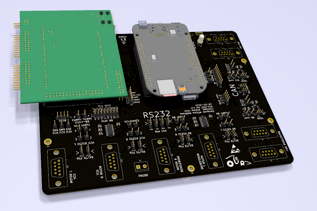
The project is made in KiCad. Which can be obtained for free! KiCad 5.0
All project files are in the Kicad/ subdirectory.
The design is made for power supply of 5V from either a MicroUSB or USBC power supply. The target current consumption by this device is 1A under load, but may be higher.
We use a SAM e70 Xplained evaluation kit as the VCU.
A Beaglebone black as the test host.
We use TCAN1042 CAN transcievers.
Both on can0 of VCU and Beaglebone.
We use MAX 3232 chips for:
LEFT: Beaglebone UART2, VCU UART 1
RIGHT: Beaglebone UART4, VCU UART 2
See pinreference_bb_vcu.ods for which beaglebone GPIOs go where (needs updating)!
We plan to use Jenkins CI, but this is yet to be figured out and made a reality.
We also have plans for a DAC daughterboard to supply analogue signals to the sensors on VCU, reference also on above document.
THINGS TO DO:
| Qty | Value | Footprint | References |
|---|---|---|---|
| 32 | TestPoint | Connector_PinHeader_2.54mm:PinHeader_1x01_P2.54mm_Vertical | TP1, TP3, TP24, TP25, TP26, TP27, TP28, TP29, TP30, TP31, TP32, TP33, TP34, TP35, TP36, TP37 +16 |
| 14 | 100n | Capacitor_SMD:C_0805_2012Metric_Pad1.15x1.40mm_HandSolder | C3, C4, C7, C8, C9, C10, C17, C18, C19, C20, C21, C22, C23, C24 |
| 8 | DB9_Male | Connector_Dsub:DSUB-9_Male_Vertical_P2.77x2.84mm_MountingHoles | J3, J4, J5, J6, J8, J9, J10, J11 |
| 8 | Jumper | Connector_PinHeader_2.00mm:PinHeader_1x03_P2.00mm_Vertical | JP1, JP2, JP3, JP4, JP8, JP10, JP11, JP12 |
| 8 | Jumper_3_Bridged12 | Connector_PinHeader_2.00mm:PinHeader_1x03_P2.00mm_Vertical | JP5, JP6, JP7, JP9, JP13, JP14, JP15, JP16 |
| 6 | MountingHole | MountingHole:MountingHole_3.2mm_M3_ISO7380_Pad | H1, H2, H3, H4, H5, H6 |
| 5 | Conn_01x08_Female | Connector_PinSocket_2.54mm:PinSocket_1x08_P2.54mm_Vertical | J501, J502, J503, J504, J505 |
| 4 | 10u | Capacitor_SMD:C_0805_2012Metric_Pad1.15x1.40mm_HandSolder | C1, C2, C5, C6 |
| 4 | 4K7 | Resistor_SMD:R_0805_2012Metric_Pad1.15x1.40mm_HandSolder | R7, R8, R9, R10 |
| 2 | 120R | Resistor_SMD:R_0805_2012Metric_Pad1.15x1.40mm_HandSolder | R1, R2 |
| 2 | 1u | Capacitor_SMD:C_0805_2012Metric_Pad1.15x1.40mm_HandSolder | C11, C12 |
| 2 | 20R | Resistor_SMD:R_0805_2012Metric_Pad1.15x1.40mm_HandSolder | R4, R5 |
| 2 | 5K1 | Resistor_SMD:R_0805_2012Metric_Pad1.15x1.40mm_HandSolder | R11, R12 |
| 2 | BeagleBone_Black_Header | project:PinHeader_2x23_P2.54mm_Vertical_Flip | P8, P9 |
| 2 | Conn_01x04_Male | Connector_PinHeader_2.54mm:PinHeader_1x04_P2.54mm_Vertical | J1, J7 |
| 2 | Conn_01x08_Male | Connector_PinHeader_2.54mm:PinHeader_1x08_P2.54mm_Vertical | J12, J13 |
| 2 | DS3231MZ | Package_SO:SOIC-8_3.9x4.9mm_P1.27mm | U6, U7 |
| 2 | MAX3232 | Package_SO:SOIC-16_3.9x9.9mm_P1.27mm | U2, U4 |
| 2 | TCAN1042HVD | Package_SO:SO-8_3.9x4.9mm_P1.27mm | U3, U5 |
| 1 | 100R | Resistor_SMD:R_0805_2012Metric_Pad1.15x1.40mm_HandSolder | R6 |
| 1 | 47R | Resistor_SMD:R_0805_2012Metric_Pad1.15x1.40mm_HandSolder | R3 |
| 1 | Battery_Cell | Battery:BatteryHolder_Keystone_1060_1x2032 | BT1 |
| 1 | Conn_01x05_Male | Connector_PinHeader_2.54mm:PinHeader_1x05_P2.54mm_Vertical | J16 |
| 1 | Conn_01x10_Female | Connector_PinSocket_2.54mm:PinSocket_1x10_P2.54mm_Vertical | J500 |
| 1 | Conn_02x18_Odd_Even | Connector_PinSocket_2.54mm:PinSocket_2x18_P2.54mm_Vertical | J507 |
| 1 | LED | Diode_SMD:D_1210_3225Metric_Pad1.42x2.65mm_HandSolder | D2 |
| 1 | LED_RABG | LED_THT:LED_D5.0mm-4_RGB | D1 |
| 1 | LOGO | footprints:OUR-Logo | G*** |
| 1 | REF3020 | Package_TO_SOT_SMD:SOT-23 | U1 |
| 1 | Screw_Terminal_01x02 | TerminalBlock:TerminalBlock_bornier-2_P5.08mm | J2 |
| 1 | USB_B_Micro | Connector_USB:USB_Micro-B_Molex-105017-0001 | J15 |
| 1 | USB_C_Receptacle | Connector_USB:USB_C_Receptacle_GCT_USB4085 | J14 |
The 122 most common of 125 parts.
Michael-Manning/E-Paper-Climate-Logger
Firmware, PCB, and enclosure for the Weathergotchi E-Paper climate logger.

Open-Smartwatch/open-smartwatch-gps
Hardware design files for the GPS version of the open-smartwatch


drpykachu/Sonar-Watch
A self-designed, home-made watch intended to tell time in a funky and unique way!

samyyy2311/CassetteCat
A music player for Android. Plays your own files, Jellyfin and Navidrome/Subsonic servers, and internet radio, with synced lyrics, an equalizer, Android Auto and a Listening Record. No account or tracking.

It measures 200 × 159 mm and has 2 copper layers, 1.6 mm thick.
125 parts, built around the MAX3232ID, TCAN1042HVD and DS3231MZ/V+. The full list of its parts is on this page, with links to each part's symbol and footprint where PCBKit's library has them.
From the OxfordUniRacing/VCU_TEST_ECAD repository on GitHub, at the commit this page was made from: the board is Kicad/VCU_tester.kicad_pcb. PCBKit opens the board in the browser, with nothing to install.
Its repository states no licence, so its author keeps all rights: ask OxfordUniRacing before reusing the design.