
2 layers
STOF sensor
OsamaAlsahli/data-glove
Low cost 16 IMU data glove with real time hand tracking and fingertip force sensing. BEng final year project
7 parts

 OsamaAlsahli/data-glove
Low cost 16 IMU data glove with real time hand tracking and fingertip force sensing. BEng final year project
STOF sensor is an open-source printed circuit board by OsamaAlsahli, from the OsamaAlsahli/data-glove repository on GitHub. It is a 2-layer board with 8 parts on 7 nets.
It is built around the TEMD7000X01. Its parts include 5 diodes, 2 connectors and 1 resistor. It belongs with the sensors and measurement and robots and motor control boards and the ESP32 boards of this library.
Low-cost, high-accuracy data glove with real-time hand motion tracking and fingertip force sensing.
Final Year Project — Osama Alsahli, BEng Electronic Engineering, University of York, 2026.
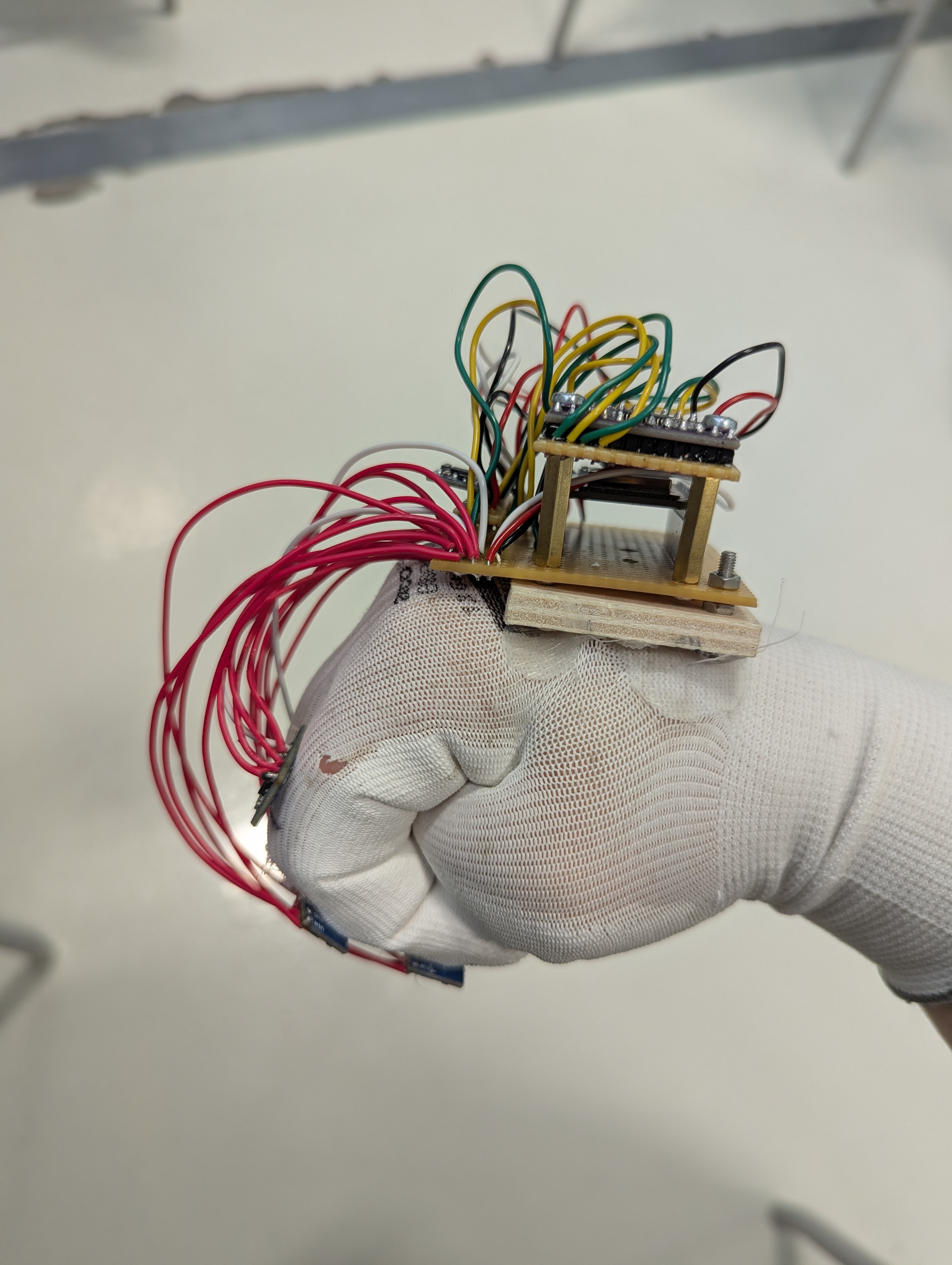
A wearable glove that captures finger and hand orientation using sixteen BNO055 9-axis IMUs (one per finger phalanx plus one on the dorsum), with soft optical tactile sensors (STOF) at the fingertips for contact force. Quaternion data is streamed from an ESP32 over USB serial to a Python bridge, which serves it to the FSGlove visualisation framework via gRPC.
Headline hardware bill of materials: 16× BNO055 IMUs, 2× TCA9548A I2C multiplexers, one ESP32 dev board, soft Ecoflex 00-30 STOF sensors at the fingertips. Total cost of purchased electronics ≈ £105.
For the full report (motivation, lit review, design, evaluation), see the accompanying BEng final report.
firmware/         ESP32 Arduino sketches (C++)
  adafruit_test/  Single-BNO055 smoke test
  tst/            Single sensor through TCA9548A
  tst2/           TCA9548A I2C scanner
  webserial_3d/   Single sensor for the Adafruit WebSerial 3D viewer
  quat_finger/    4-IMU single-finger demo
  quat/           Full 16-IMU glove firmware
  fsglove-main/   FSGlove visualisation framework (third-party, included
                  for reproducibility - see Licence section)

bridge/           Python serial-to-gRPC bridge
  bridge.py            Full 16-sensor bridge (the one you actually run)
  bridge_finger.py     Incomplete 4-sensor variant, kept for reference
  read_imu.py          Minimal serial quaternion printer
  visualise_imu.py     Live OpenGL "bone" visualiser

images/           Prototype photos, kinematic model, Gantt chart
schematics/ PCB / schematic designs (KiCad) for STOF and main boardfirmware/quat/quat.ino in the Arduino IDE.The single-sensor bring-up sketches (adafruit_test, tst, tst2,
webserial_3d) are useful for verifying hardware before flashing the full
build.
cd bridge
pip install pyserial grpcio
# Generate imu_packet_pb2.py / imu_packet_pb2_grpc.py from the FSGlove proto
# (imu_packet.proto lives inside firmware/fsglove-main).
python bridge.py
The bridge listens on localhost:18890; start FSGlove afterwards and it
will subscribe to the stream.
If you want to drive the visualiser without hardware, swap the
target=read_serial line in bridge.py's main() for
target=generate_fake_serial.
The code I wrote (everything under firmware/ except fsglove-main/, and
everything under bridge/) is released for academic and personal use.
firmware/fsglove-main/ is included for reproducibility only and is the
work of its original authors — see its own README and licence inside that
folder or (https://github.com/davidliyutong/fsglove). The SMPLH model weights (SMPLH_male.pkl, SMPLH_female.pkl)
required by FSGlove are not included in this repo. To obtain them and
get FSGlove running, follow the setup instructions in the upstream FSGlove
repository (https://github.com/davidliyutong/fsglove); the project page
is at https://sites.google.com/view/fsglove/.
firmware/quat/quat.ino was written
assuming one 16 channel multiplexer, but the final hardware splits the
16 IMUs across two TCA9548As (each with 8 channels). Reading sensors 8 to 15
therefore needs a second multiplexer select layer that this build does
not yet implement. The limitation is flagged inline with a NOTE: comment.
The single finger and 8 sensor paths are fully working.bridge/bridge_finger.py is an unfinished early version of the bridge,
kept for historical reference. The working bridge is bridge/bridge.py.| Qty | Value | Footprint | References |
|---|---|---|---|
| 4 | TEMD7000X01 | LED_SMD:LED_0805_2012Metric | D1, D2, D3, D4 |
| 2 | Conn_01x03 | Connector_Wire:SolderWire-0.1sqmm_1x03_P3.6mm_D0.4mm_OD1mm | J1, J2 |
| 1 | 100 | Resistor_SMD:R_0603_1608Metric | R1 |
| 1 | LED | LED_SMD:LED_0805_2012Metric | LED1 |
OsamaAlsahli/data-glove
Low cost 16 IMU data glove with real time hand tracking and fingertip force sensing. BEng final year project

OsamaAlsahli/data-glove
Low cost 16 IMU data glove with real time hand tracking and fingertip force sensing. BEng final year project

OsamaAlsahli/data-glove
Low cost 16 IMU data glove with real time hand tracking and fingertip force sensing. BEng final year project


joeycastillo/Sensor-Watch
A board replacement for the classic Casio F-91W wristwatch

rusefi/rusefi
rusefi - GPL internal combustion engine control unit

hoglet67/RGBtoHDMI
Bare-metal Raspberry Pi project that provides pixel-perfect sampling of Retro Computer RGB/YUV video and conversion to HDMI

shanteacontrols/OpenDeck
A platform for building interactive control and sensing devices using MIDI and OSC built with Zephyr RTOS.

hackclub/OnBoard
💡 Join 1,000 teenagers and make your first PCB with a $100 grant!

dangiu/PicoMemcard
Emulating PSX Memory Card (or controller) using a Raspberry Pi Pico
8 parts, built around the TEMD7000X01. The full list of its parts is on this page, with links to each part's symbol and footprint where PCBKit's library has them.
From the OsamaAlsahli/data-glove repository on GitHub, at the commit this page was made from: the board is schematics/STOF_v1/STOF_sensor.kicad_pcb and its schematic schematics/STOF_v1/STOF_sensor-backups/STOF_sensor-2026-04-01_190337/STOF_sensor.kicad_sch. PCBKit opens the board in the browser, with nothing to install.
Its repository states no licence, so its author keeps all rights: ask OsamaAlsahli before reusing the design.