2 layers
 OpenBotBrain/mcu-board
Some design notes for an MCU board.
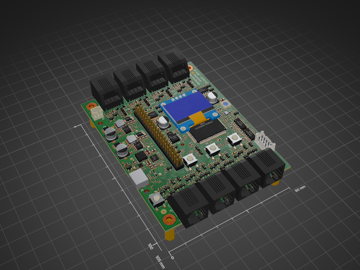
RobotLegoController is an open-source printed circuit board by OpenBotBrain, from the OpenBotBrain/mcu-board repository on GitHub. It is a 4-layer board of 80 × 105 mm with 725 parts on 352 nets, routed with 5,697 tracks and 784 vias.
It is built around the LMV324, DRV8833PWP and PAM2423AECADJR, with the FUSB302B01MPX, W25X40CLSSIG and SN74LVC1G14DBV among its other parts. Its parts include 237 resistors, 182 capacitors, 65 diodes, 30 transistors and 23 ICs. It belongs with the microcontroller boards boards and the STM32 boards of this library.


Some design notes for an MCU board... Deeply WIP.
STM32 Cortex M4 - May be
4 motor control ports (EV3 compatible)
4 sensor control ports (EV3 compatible)
Raspberry Pi pin-out connector (enough to communicate with Raspberry pi Zero, does not need full support)
SD card (SPI interface enough/SDIO nice to have but requires supported MCU)
Accelerometer (could be external)
STEMMA QT connector (nice to have)
Some informative display and a couple of LEDs (nice to have)
A couple of buttons for interface (nice to have also)
Lego "compatible" physical shape.
| Qty | Value | Footprint | References |
|---|---|---|---|
| 137 | S1mm | TestPoint:TestPoint_Pad_1.0x1.0mm | TP1, TP10, TP11, TP100, TP101, TP103, TP104, TP105, TP106, TP107, TP108, TP109, TP110, TP111, TP112, TP113 +121 |
| 65 | 10K | Resistor_SMD:R_0402_1005Metric | R1, R13, R14, R110, R111, R112, R114, R124, R125, R134, R135, R140, R141, R142, R143, R144 +49 |
| 53 | 100n | Capacitor_SMD:C_0402_1005Metric | C1, C10, C12, C14, C113, C141, C142, C143, C144, C145, C146, C166, C167, C168, C169, C170 +37 |
| 46 | 100K | Resistor_SMD:R_0402_1005Metric | R102, R103, R106, R108, R117, R119, R126, R127, R132, R133, R148, R149, R154, R167, R169, R174 +30 |
| 46 | 330 | Resistor_SMD:R_0402_1005Metric | R10, R11, R12, R100, R101, R104, R105, R107, R109, R113, R115, R128, R129, R130, R131, R150 +30 |
| 38 | 330p | Capacitor_SMD:C_0402_1005Metric | C100, C101, C102, C103, C104, C105, C106, C107, C115, C116, C120, C121, C122, C123, C124, C125 +22 |
| 29 | 1u 16V | Capacitor_SMD:C_0603_1608Metric | C2, C16, C17, C19, C110, C111, C112, C114, C119, C132, C135, C140, C157, C160, C165, C181 +13 |
| 25 | 10n | Capacitor_SMD:C_0402_1005Metric | C15, C108, C109, C117, C118, C128, C129, C133, C134, C138, C139, C150, C158, C159, C163, C164 +9 |
| 25 | 2K4 | Resistor_SMD:R_0402_1005Metric | R21, R22, R120, R121, R136, R137, R170, R171, R178, R179, R192, R193, R213, R214, R227, R228 +9 |
| 24 | 4K7 | Resistor_SMD:R_0402_1005Metric | R122, R123, R138, R139, R172, R173, R176, R177, R182, R183, R190, R191, R196, R197, R211, R212 +8 |
| 24 | BAT54S | Package_TO_SOT_SMD:SOT-23 | D13, D14, D15, D16, D19, D20, D23, D24, D27, D28, D29, D30, D33, D34, D37, D38 +8 |
| 22 | ESD9B5.0ST5G | Diode_SMD:D_SOD-923 | D17, D18, D21, D22, D25, D26, D31, D32, D35, D36, D39, D40, D41, D42, D45, D46 +6 |
| 19 | 2N7002 | Package_TO_SOT_SMD:SOT-23 | Q13, Q15, Q16, Q19, Q20, Q27, Q28, Q29, Q30, Q31, Q32, Q33, Q34, Q35, Q36, Q37 +3 |
| 16 | 22 | Resistor_SMD:R_0402_1005Metric | R5, R9, R28, R29, R30, R32, R34, R36, R37, R38, R44, R46, R48, R49, R52, R152 |
| 11 | 10u | Capacitor_SMD:C_0805_2012Metric | C9, C49, C50, C51, C56, C73, C74, C75, C77, C78, C79 |
| 11 | 10u 16V | Capacitor_SMD:C_0805_2012Metric | C40, C44, C57, C59, C61, C64, C65, C67, C70, C147, C172 |
| 11 | BSS84 | Package_TO_SOT_SMD:SOT-23 | Q1, Q2, Q3, Q5, Q6, Q9, Q10, Q11, Q12, Q17, Q18 |
| 10 | TH1mm | TestPoint:TestPoint_THTPad_1.0x1.0mm_Drill0.5mm | TP15, TP17, TP19, TP21, TP23, TP28, TP133, TP146, TP147, TP149 |
| 8 | 30mA | Resistor_SMD:R_0603_1608Metric | F3, F4, F5, F6, F7, F8, F9, F10 |
| 8 | RJ12 | Connector_RJ:RJ12_Amphenol_54601 | J7, J8, J9, J10, J11, J12, J13, J14 |
| 8 | SD12_SOD323 | Diode_SMD:D_SOD-323 | D49, D50, D51, D52, D61, D62, D63, D64 |
| 8 | SN74LVC1G14DBV | Package_TO_SOT_SMD:SOT-23-5 | U13, U14, U15, U16, U19, U20, U21, U22 |
| 6 | LED | LED_SMD:LED_0402_1005Metric | D1, D2, D3, D8, D9, D10 |
| 5 | 220K | Resistor_SMD:R_0402_1005Metric | R42, R116, R118, R166, R168 |
| 5 | 4u7 16V | Capacitor_SMD:C_0603_1608Metric | C11, C13, C60, C149, C174 |
| 4 | 0.43 | Resistor_SMD:R_0805_2012Metric | R207, R208, R242, R243 |
| 4 | 100uF 16V | Capacitor_SMD:CP_Elec_6.3x5.2 | C66, C69, C148, C173 |
| 4 | 3mm | MountingHole:MountingHole_3.2mm_M3_Pad | H1, H2, H3, H4 |
| 4 | 51K | Resistor_SMD:R_0402_1005Metric | R60, R63, R64, R66 |
| 4 | Fiducial | Fiducial:Fiducial_1mm_Mask3mm | FID1, FID2, FID3, FID4 |
| 4 | LMV324 | Package_SO:SOIC-14_3.9x8.7mm_P1.27mm | U10, U11, U12, U18 |
| 4 | SW_Omron_B3FS | Button_Switch_SMD:SW_Push_1P1T_NO_6x6mm_H9.5mm | SW1, SW2, SW3, SW5 |
| 2 | 2.2n | Capacitor_SMD:C_0402_1005Metric | C84, C85 |
| 2 | 29K4 | Resistor_SMD:R_0402_1005Metric | R59, R67 |
| 2 | 47p | Capacitor_SMD:C_0402_1005Metric | C82, C83 |
| 2 | 6.8uH 3.6A | Inductor_SMD:L_Ferrocore_DLG-0504 | L2, L3 |
| 2 | 6p8 | Capacitor_SMD:C_0402_1005Metric | C21, C22 |
| 2 | 8V 2A | Resistor_SMD:R_1812_4532Metric | F1, F2 |
| 2 | DRV8833PWP | Package_SO:HTSSOP-16-1EP_4.4x5mm_P0.65mm_EP3.4x5mm_Mask2.46x2.31mm_ThermalVias | U17, U23 |
| 2 | ESD5Zxx | Diode_SMD:D_SOD-523 | D4, D5 |
| 2 | FSV330AF | Diode_SMD:D_SOD-128 | D11, D12 |
| 2 | PAM2423AECADJR | Package_SO:SOIC-8-1EP_3.9x4.9mm_P1.27mm_EP2.29x3mm_ThermalVias | U8, U9 |
| 1 | 1.2uH 6.5A | Inductor_SMD:L_Chilisin_BMRA00050520 | L1 |
| 1 | 8Z-24.000MAAJ-T | Crystal:Crystal_SMD_Abracon_ABM10-4Pin_2.5x2.0mm | Y2 |
| 1 | AP2127K-3.3 | Package_TO_SOT_SMD:SOT-23-5 | U7 |
| 1 | BQ25601 | Package_DFN_QFN:Texas_S-PWQFN-N24_EP2.7x2.7mm_ThermalVias | U6 |
| 1 | Conn_01x02 | Connector_JST:JST_PH_B2B-PH-K_1x02_P2.00mm_Vertical | J4 |
| 1 | DF11-10DP-2DSA | Connector_JST:JST_PHD_B10B-PHDSS_2x05_P2.00mm_Vertical | J1 |
| 1 | FUSB302B01MPX | Package_DFN_QFN:WQFN-14-1EP_2.5x2.5mm_P0.5mm_EP1.45x1.45mm | U5 |
| 1 | Inolux_IN-PI554FCH | LED_SMD:LED_Inolux_IN-PI554FCH_PLCC4_5.0x5.0mm_P3.2mm | D65 |
| 1 | LSM6DSL | Package_LGA:LGA-14_3x2.5mm_P0.5mm_LayoutBorder3x4y | U1 |
| 1 | Raspberry_Pi_2_3 | Connector_PinHeader_2.54mm:PinHeader_2x20_P2.54mm_Vertical | J2 |
| 1 | SSD1306 | SSD1306:128x64OLED | U3 |
| 1 | STM32L496ZGTx | Package_QFP:LQFP-144_20x20mm_P0.5mm | U2 |
| 1 | USB_C_Receptacle_USB2.0 | Connector_USB:USB_C_Receptacle_Palconn_UTC16-G | J3 |
| 1 | W25X40CLSS | Package_SO:SOIC-8_5.275x5.275mm_P1.27mm | U4 |
| 1 | ~ | CustomLibrary:sggtav_logo | SYMBOL1 |
| 1 | ~ | CustomLibrary:lego_robot_controller | SYMBOL2 |
| 1 | ~ | CustomLibrary:open_source | SYMBOL3 |

jncronin/gk
This respository provides PCB schematics, firmware and debugging support for the gkv4 handheld game console and its operating system, gkos. For the original STM32H7S7-based gk, see README-v3.md.


CrashOverride85/zc95
4 channel EStim box inspired by the mk312bt, with Lua scripting support


It measures 80 × 105 mm and has 4 copper layers, 1.6 mm thick.
725 parts, built around the LMV324, DRV8833PWP, PAM2423AECADJR and FUSB302B01MPX. The full list of its parts is on this page, with links to each part's symbol and footprint where PCBKit's library has them.
From the OpenBotBrain/mcu-board repository on GitHub, at the commit this page was made from: the board is PCB-RevA/RobotLegoController/RobotLegoController.kicad_pcb and its schematic PCB-RevA/RobotLegoController/01-Microcontroller and Extras.kicad_sch. PCBKit opens the board in the browser, with nothing to install.
Its repository states no licence, so its author keeps all rights: ask OpenBotBrain before reusing the design.