4 layers45 × 75 mm

 OmkarKnkr/Atlas-S3-DevBoard3
Atlas S3 DevBoard is a custom ESP32-S3 development board designed from the ground up with an emphasis on compactness, usability, and clean PCB design practices. The board integrates essential development features while maintaining a layout suitable for embedded applications and future expansion.
DevBoard is an open-source printed circuit board by OmkarKnkr, from the OmkarKnkr/Atlas-S3-DevBoard repository on GitHub. It is a 4-layer board of 27.4 × 65.2 mm with 52 parts on 87 nets, routed with 776 tracks and 166 vias.
It is built around the ESP32-S3-WROOM-1-N8, USBLC6-2SC6 and BMI088, with the SS8050 and SK6812MINI-E among its other parts. Its parts include 15 resistors, 13 capacitors, 6 ICs, 5 connectors and 4 diodes. It belongs with the microcontroller boards boards and the ESP32 boards of this library.


A compact, four-layer ESP32-S3 development board designed for embedded systems development, rapid prototyping, and sensor-based applications.
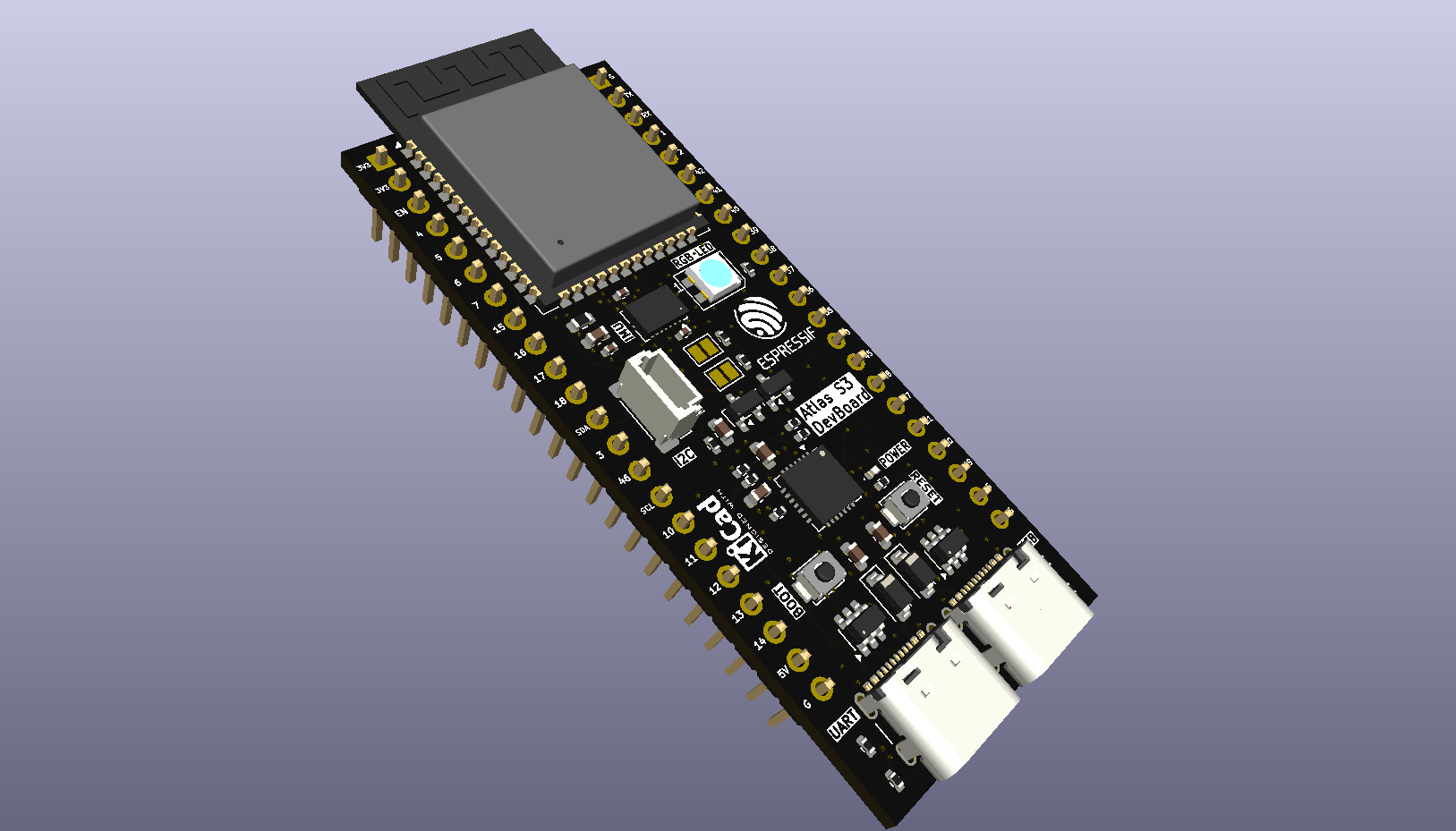
Atlas S3 DevBoard is a custom ESP32-S3 development board designed from the ground up with an emphasis on compactness, usability, and clean PCB design practices. The board integrates essential development features while maintaining a layout suitable for embedded applications and future expansion.
This project was created to demonstrate the complete embedded hardware design workflow—from schematic capture and PCB layout to documentation and hardware validation.
| Component | Description |
|---|---|
| MCU | ESP32-S3-WROOM-1 |
| USB | USB Type-C |
| Power | 5 V USB Input |
| Regulator | LD1117 |
| Sensor | Bosch BMI088 IMU |
| Expansion | Headers |
| PCB | 4 Layers |
| Design Software | KiCad 10 |
The following table lists the default GPIO assignments for the onboard peripherals integrated into the Atlas S3 DevBoard.
| Signal | ESP32-S3 GPIO | Description |
|---|---|---|
| SCK | GPIO12 | SPI Clock (FSPICLK) |
| MOSI (SDI) | GPIO11 | SPI Master Out, Slave In (FSPID) |
| MISO (SDO) | GPIO13 | SPI Master In, Slave Out (FSPIQ) |
| ACC_CS | GPIO10 | Accelerometer Chip Select |
| GYR_CS | GPIO14 | Gyroscope Chip Select |
| ACC_DRDY (INT1) | GPIO6 | Accelerometer Data Ready Interrupt |
| GYR_DRDY (INT3) | GPIO7 | Gyroscope Data Ready Interrupt |
| Signal | ESP32-S3 GPIO | Description |
|---|---|---|
| DIN | GPIO38 | Addressable RGB LED Data Input |
| Signal | ESP32-S3 GPIO | Description |
|---|---|---|
| SDA | GPIO8 | I²C Data |
| SCL | GPIO9 | I²C Clock |
Note: The ESP32-S3 does not provide dedicated I²C pins. GPIO8 (SDA) and GPIO9 (SCL) are configured as the default I²C interface for the onboard STEMMA QT/Qwiic connector and can be reassigned in software if required.
Atlas-S3
│
├── Hardware
│   ├── Assembly
│   ├── Gerbers
│   ├── KiCad
│   └── PDFs
│
├── Documentation
│   ├── Atlas S3 Devboard.pdf
│   └── Images
│
└── README.md
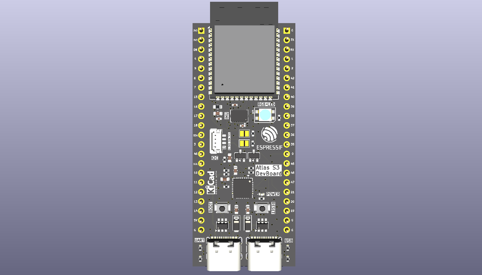
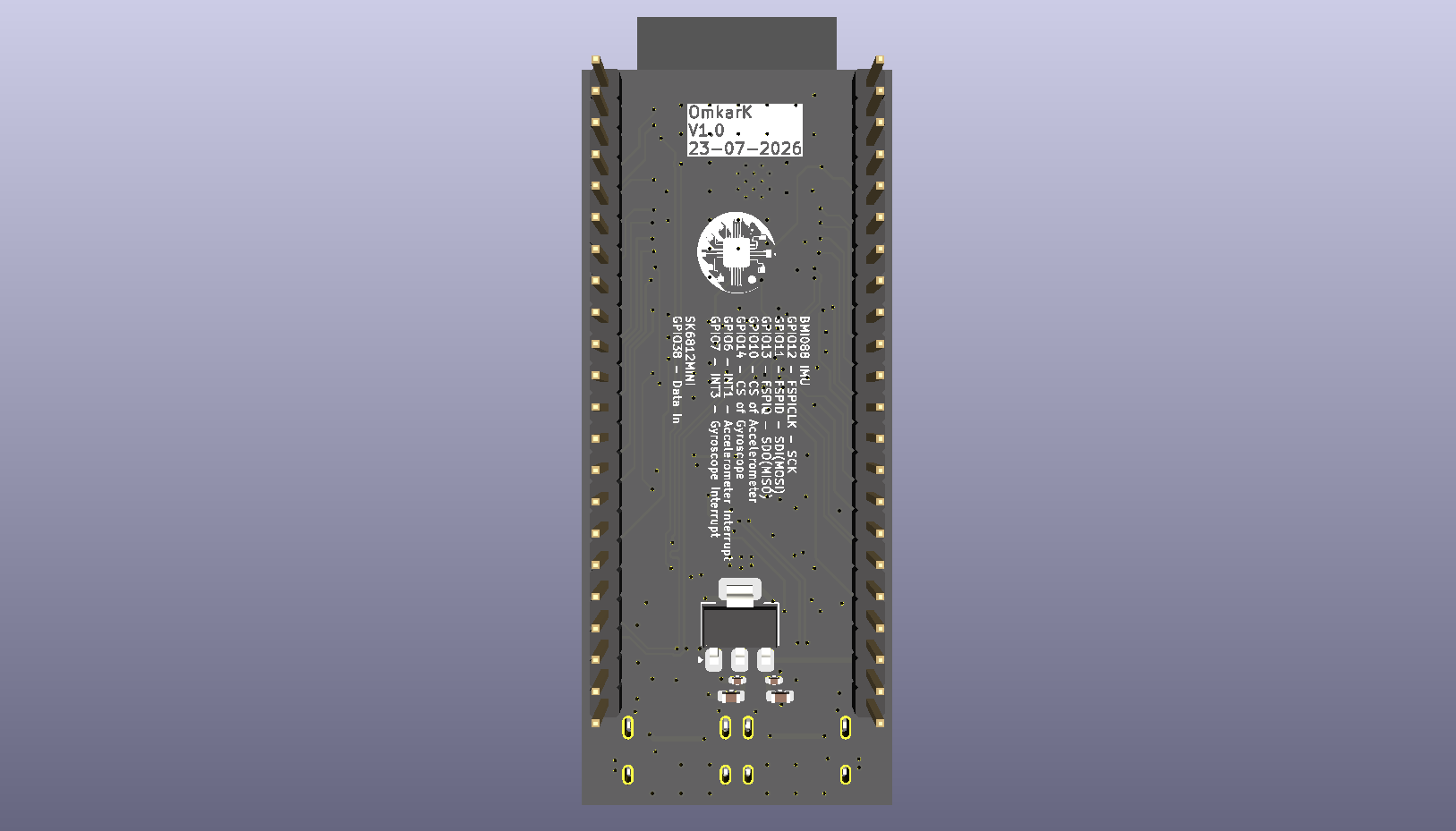
The repository includes:
Hardware Revision: V1.0
| Stage | Status |
|---|---|
| Schematic Design | Complete |
| PCB Layout | Complete |
| Design Review | Complete |
| Manufacturing Files | Complete |
| PCB Fabrication | Pending |
| Assembly | Pending |
| Bring-up | Pending |
| Firmware Examples | Planned |
Omkar Vinod Kunkolienker
Electronics & Telecommunication Engineering Goa College of Engineering
GitHub: OmkarKnkr
LinkedIn: OmkarKnkr
This project was developed as a personal embedded systems and PCB design project to strengthen practical hardware design skills and showcase a complete engineering workflow.
Notice
This repository is shared for educational and portfolio purposes. The hardware design and associated documentation remain the intellectual property of the author. Please contact the author before reproducing, modifying, or commercially using this work.
| Qty | Value | Footprint | References |
|---|---|---|---|
| 6 | 10u | Capacitor_SMD:C_0603_1608Metric | C1, C2, C3, C5, C7, C9 |
| 5 | 100n | Capacitor_SMD:C_0402_1005Metric | C4, C6, C10, C11, C12 |
| 5 | 5k1 | Resistor_SMD:R_0402_1005Metric | R1, R2, R3, R4, R5 |
| 3 | 10k | Resistor_SMD:R_0402_1005Metric | R10, R11, R14 |
| 3 | LOGO | LOGO | G***, G***, G*** |
| 2 | 1N5819 | Diode_SMD:D_SOD-123 | D1, D2 |
| 2 | 1u | Capacitor_SMD:C_0603_1608Metric | C8, C13 |
| 2 | 4k7 | Resistor_SMD:R_0402_1005Metric | R15, R16 |
| 2 | SS8050 | Package_TO_SOT_SMD:SOT-23 | Q1, Q2 |
| 2 | USBLC6-2SC6 | Package_TO_SOT_SMD:SOT-23-6 | U4, U5 |
| 2 | USB_C_Receptacle_USB2.0_16P | Connector_USB:USB_C_Receptacle_GCT_USB4105-xx-A_16P_TopMnt_Horizontal | J1, J2 |
| 1 | 0 | Resistor_SMD:R_0603_1608Metric | R12 |
| 1 | 0 | Resistor_SMD:R_0402_1005Metric | R13 |
| 1 | 1k | Resistor_SMD:R_0402_1005Metric | R8 |
| 1 | 22k1 | Resistor_SMD:R_0402_1005Metric | R6 |
| 1 | 47k5 | Resistor_SMD:R_0402_1005Metric | R7 |
| 1 | BMI088 | Package_LGA:Bosch_LGA-16_4.5x3mm_P0.5mm_LayoutBorder7x1y_ClockwisePinNumbering | U6 |
| 1 | BOOT | Button_Switch_SMD:SW_SPST_B3U-1000P | SW1 |
| 1 | CP2102N-Axx-xQFN28 | Package_DFN_QFN:QFN-28-1EP_5x5mm_P0.5mm_EP3.35x3.35mm | U3 |
| 1 | ESP32-S3-WROOM-1 | RF_Module:ESP32-S3-WROOM-1 | U1 |
| 1 | I2C | Connector_JST:JST_SH_BM04B-SRSS-TB_1x04-1MP_P1.00mm_Vertical | J5 |
| 1 | LD1117S33TR_SOT223 | Package_TO_SOT_SMD:SOT-223-3_TabPin2 | U2 |
| 1 | Left | Connector_PinHeader_2.54mm:PinHeader_1x22_P2.54mm_Vertical | J4 |
| 1 | Power | LED_SMD:LED_0402_1005Metric | D3 |
| 1 | RESET | Button_Switch_SMD:SW_SPST_B3U-1000P | SW2 |
| 1 | Right | Connector_PinHeader_2.54mm:PinHeader_1x22_P2.54mm_Vertical | J3 |
| 1 | SCL Jumper | Jumper:SolderJumper-2_P1.3mm_Open_Pad1.0x1.5mm | JP2 |
| 1 | SDA Jumper | Jumper:SolderJumper-2_P1.3mm_Open_Pad1.0x1.5mm | JP3 |
| 1 | SK6812MINI | LED_SMD:LED_SK6812MINI_PLCC4_3.5x3.5mm_P1.75mm | D4 |

Maxandersen1/ESP32-S3-Flight_Controller
Custom ESP32 Flight Controller using BMI088 & BMP388 sensors. Hardware and firmware built from the ground up.

bismarx-v1/Sumec-MiniSumo-HW
SUMEC is a MiniSumo robot designed by SPŠ na Proseku students. This repository contains hardware source for this project - PCB files and other electronics.

LighthouseXy/VoxConductor
VoxConductor — ESP32-S3 desktop intelligent voice hub with LVGL, ASR, DeepSeek, streaming TTS, weather and microSD logging


pacman314159/OISP-Drone-Research
mermaid stateDiagram-v2 [] --> POWERON POWERON --> BOOTINIT: Power Applied / Reset BOOTINIT --> SENSORCALIBRATION: Hardware Self-Test Pass BOOTINIT --> SYSTEMERROR: Self-Test Fail SENSORCALIBRATION --> DISARMED…

nathanfraske/CEC-Platform
ONE board file, kept current by the wave (owner directive 2026-07-25: "the current best should be placed into a candidate folder per board and kept current with only one board ideally so we have a reference").

It measures 27.4 × 65.2 mm and has 4 copper layers, 1.6 mm thick.
52 parts, built around the ESP32-S3-WROOM-1-N8, USBLC6-2SC6, BMI088 and SS8050. The full list of its parts is on this page, with links to each part's symbol and footprint where PCBKit's library has them.
From the OmkarKnkr/Atlas-S3-DevBoard repository on GitHub, at the commit this page was made from: the board is Hardware/KiCad/DevBoard.kicad_pcb and its schematic Hardware/KiCad/DevBoard.kicad_sch. PCBKit opens the board in the browser, with nothing to install.
Its repository states no licence, so its author keeps all rights: ask OmkarKnkr before reusing the design.